
Leon Mk1
|

| 1 - | Conrod bolt, 30 Nm + 1/ further 4 turn (90°) |
| q | replace |
| q | Oil threads and contact surface. |
| q | To measure the radial play, use used bolts |
| q | To measure radial clearance, tighten to 30 Nm but do not turn further |
| 2 - | Bolt with pressure relief valve, 27 Nm |
| q | Opening pressure 1.3 ... 1.6 bar. |
| 3 - | Oil spray jet |
| q | For cooling the piston |
| 4 - | Conrod bearing cap |
| q | Mark cylinder number -B- |
| q | Fitting position: The marks -A- should point towards the pulley |
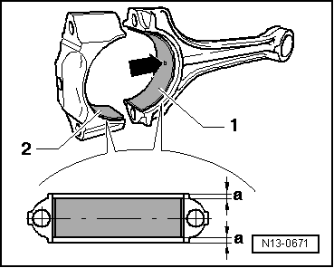
| 5 - | Bearing shells |
| q | Upper bearing shell with a drilled hole for lubricating the piston pin |
| q | Installation position → Fig. |
| q | Do not interchange used bearing shells (mark). |
| q | New axial play: 0.10 ... 0.35 mm. Wear limit: 0.40 mm |
| q | Recheck the radial play using a Plastigage New: 0.02 ... 0.06 mm. Wear limit: 0.09 mm do not rotate the crankshaft during the radial play measurement |
| 6 - | Conrod |
| q | With industrially cracked conrod cap. |
| q | Renew as set only. |
| q | Mark cylinder number -B- |
| q | Fitting position: The marks -A- should point towards the pulley |
| q | With a drilled hole for lubricating the piston pin |
| 7 - | Circlip |
| 8 - | Piston pin |
| q | If difficult to remove, heat piston to 60 °C. |
| q | Removing and installing with the awl -T20019- |
| 9 - | Piston |
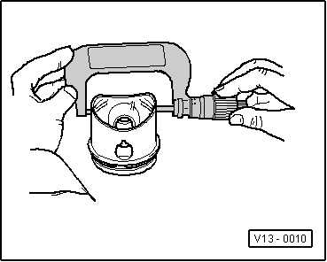
| q | check → Fig. |
| q | Mark installation position and cylinder number. |
| q | Arrow on piston crown points to belt pulley end. |
| q | Install using piston ring clamp. |
| q | Piston and cylinder dimensions → Chapter |
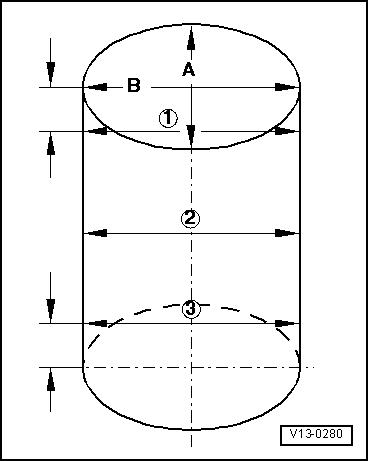
| q | Checking cylinder bores → Fig.. |
| 10 - | Piston rings |
| q | Displace the gaps at 120° from each other |
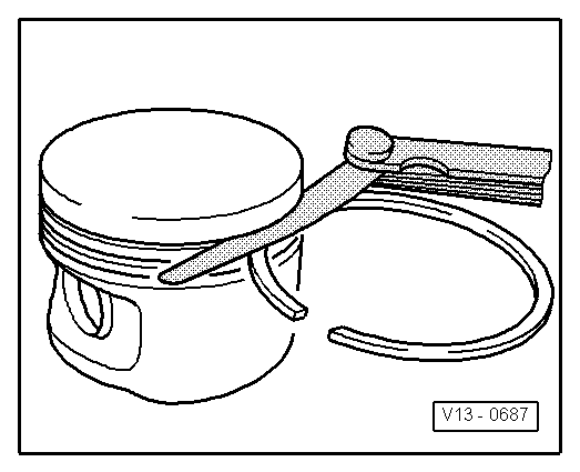
| q | Use piston ring pliers to remove and install. |
| q | „TOP“ faces towards piston crown. |
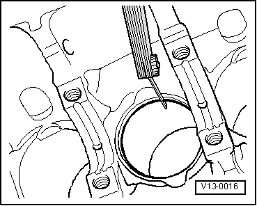
| q | Piston ring ends: check clearance → Fig. |
| q | Checking ring-to-groove clearance → Fig.. |
| Piston ring dimensions in mm | new | Wear limit |
| Compression ring | 0.20 ... 0.40 | 0.8 |
| Oil scraping ring | 0.25 ... 0.50 | 0.8 |
|
|
| Piston ring dimensions in mm | new | Wear limit |
| Compression ring | 0.06 ... 0.09 | 0.20 |
| Oil scraping ring | 0.03 ... 0.06 | 0.15 |
|
|
 Note
Note
|
|
|
|