
Leon Mk1
|
| Consult the equivalence table for tools and equipment according to applicability among Seat / VW / Audi / Skoda → Chapter. |
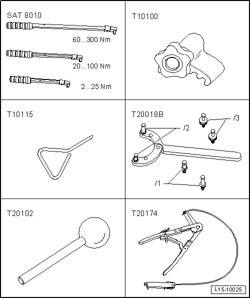
| Special tools and workshop equipment required |
| t | Torque wrench kit -SAT 8010-, see equivalent → Anchor |
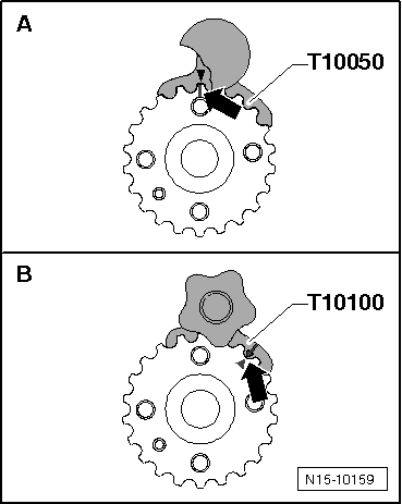
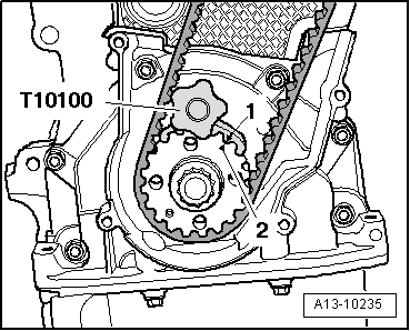
| t | counterhold -T10100-, see equivalent → Anchor |
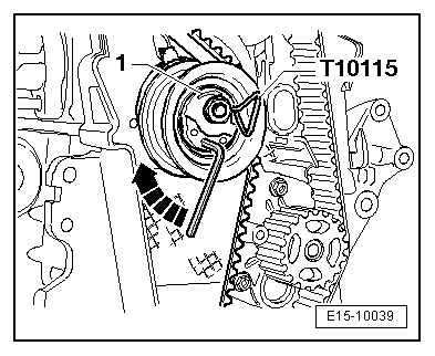
| t | Hose clamp -T10115-, see equivalent → Anchor |
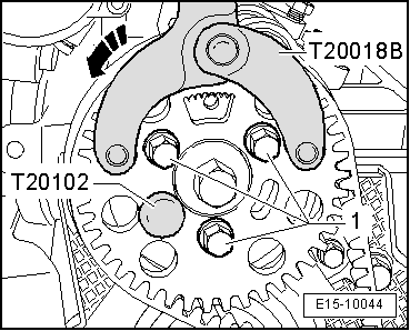
| t | Hose clamp -T20018B-, see equivalent → Anchor |
| t | Hose clamp -T20102-, see equivalent → Anchor |
| t | Base -T20174-, see equivalent → Anchor |
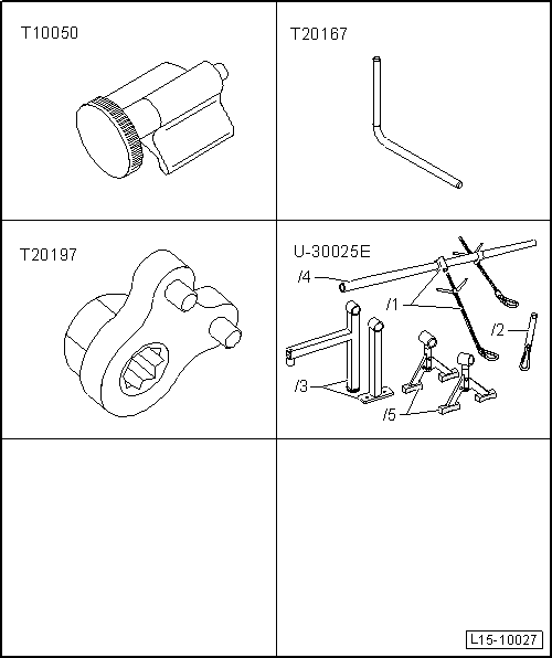
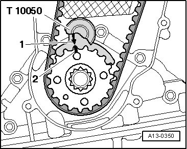
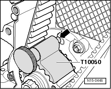
| t | Hose clamp -T10050-, see equivalent → Anchor |
| t | Hose clamp -T20167-, see equivalent → Anchor |
| t | Turning tool -T20197-, see equivalent → Anchor |
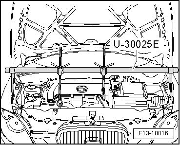
| t | Socket -U 30025E-, see equivalent → Anchor |
 Note
Note
|
|
|
|
|
|
 WARNING
|
|
|
|
Note |
|
|
|
|
|
|
|
|
|
|
|
|
|
Note
|
|
|
|
Note
|
|
|
|
|
|
|
|
|
|
|
|
Note
|
|
Note |
|
Note
Note |
|
|
|
Note
|
|
Note
|
|
|
|
|
|
|
|
|
|
Note
|
|
|
|
|
|
|
|
Note
|
|
|
|
|
|
|
|
|
|
Note
|
|
|
|