seat Workshop Repair Guides

SEAT Workshop Service and Repair Manuals

Removing and installing cylinder head > < Toothed belt: removing and installing - vehicle ? 05.05 with small engine support
Removing and installing toothed belt - vehicles ► 06.05 with large engine support
t  Removing → Anchor
t  Installing → Anchor
t  Tightening torques → Anchor
   
Consult the equivalence table for tools and equipment according to applicability among Seat / VW / Audi / Skoda → Chapter.
Special tools and workshop equipment required
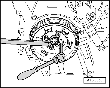
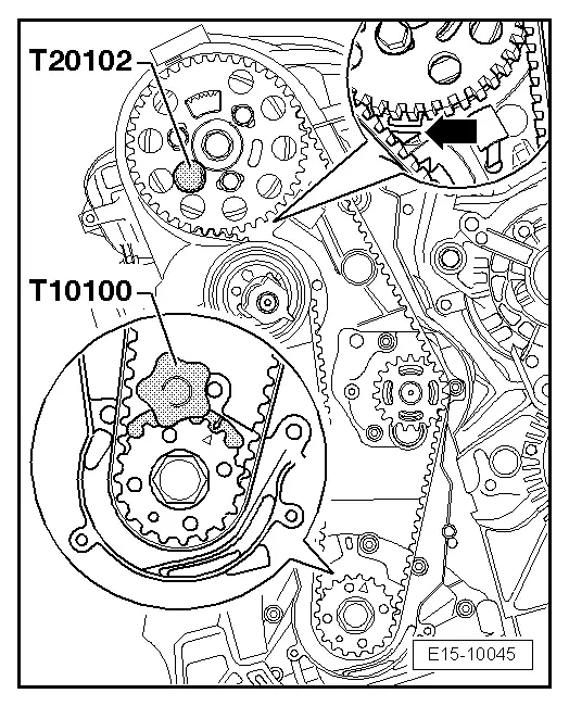
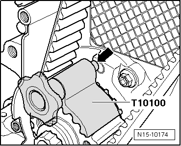
t  counterhold -T10100-, see equivalent → Anchor
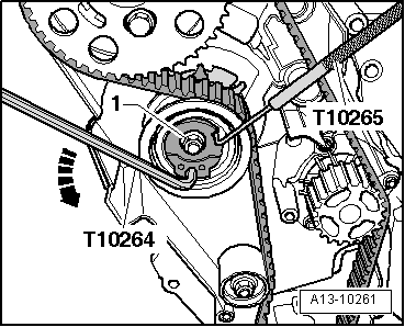
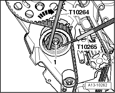
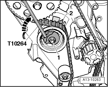
t  Spanner -T10264-, see equivalent → Anchor
t  Hose clamp -T10265-, see equivalent → Anchor
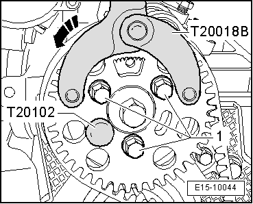
t  Hose clamp -T20018B-, see equivalent → Anchor
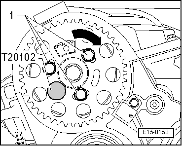
t  Hose clamp -T20102-, see equivalent → Anchor
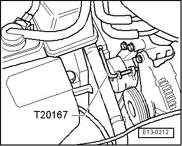
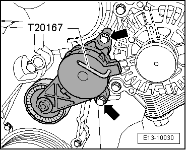
t  Hose clamp -T20167-, see equivalent → Anchor

Removing
   
Engine code letters BJB, BKC, BXE, BXF
–  Pull the oil dipstick -1- out of the guide tube.
–  Lift the engine cover by the sides -arrows 2- and pull it out forwards -arrow 3-.
–  Replace the oil dipstick in the guide tube.
  E10-10002
–  Lay the lines -1 ... 3- on the air pipe open.
–  Remove air duct by lifting retaining clips -arrows- slightly.
  Note
The coolant hose -1- and fuel pipes -2- and -3- must remain connected.
  A10-1838
Select engine identification letters BLS
–  First remove the outer cover -1- and then the inner cover -2- upwards equally.
  WARNING
t  For those vehicles fitted with an injector pump, the temperature of the fuel and the fuel lines may reach up to 100 ºC in extreme cases. Before opening the duct connections, allow the fuel to cool otherwise there is a risk of severe burns.
t  Wear eye and hand protection when performing any type of repair work on the fuel system!
  E10-10038
–  Disconnect the fuel supply hose -2- and return hose -1- from the fuel pipes.
–  Remove the coolant hoses -3- .
  A10-10371
–  Remove bolt -1-.
–  Remove air duct by lifting retaining clips -arrows- slightly.
Continued for all vehicles
  WARNING
t  For those vehicles fitted with an injector pump, the temperature of the fuel and the fuel lines may reach up to 100 ºC in extreme cases. Before opening the duct connections, allow the fuel to cool otherwise there is a risk of severe burns.
t  Wear eye and hand protection when performing any type of repair work on the fuel system!
  A10-10266
–  Disconnect fuel supply -2- and fuel return pipes -1-, by pulling on the release tabs.
  A20-1118
–  Release the fittings and pull fuel filter with hoses attached upwards out of the bracket -arrow- and secure to the side.
  A10-1685
–  Unscrew bracket -3- for fuel filter.
–  Unscrew bolts -2- for windscreen washer tank filler neck.
–  Unplug connector found on coolant expansion tank -1-.
–  Unbolt coolant expansion tank -1- and lay it on the cylinder head cover with hoses connected.
  Note
  A13-0646
Before removing the ribbed belt, mark its running direction with chalk or with a felt tipped pen. Running a used belt in the opposite direction could destroy it.
–  To slacken the Poly-V belt, turn the tensioner in the direction of the arrow.
  A13-0083
–  Lock Poly-V belt tensioner using the tool -T20167-.
–  Remove poly V-belt.
  E13-0212
–  Extract the bolts -arrows- and remove the Poly V-belt tensioner.
  E13-10030
–  Remove upper notched belt guard by releasing retaining clips -arrows-.
  A13-0394
–  Fit the centre noise insulation -fasteners 1 ... 3-.
  A10-1565
–  Fit the right noise insulation -fastening parts 1 ... 3-.
  A10-1566
Engine code letters BJB, BKC, BXE, BXF
–  Unscrew bolts -1- and -2-.
–  Remove the right hand side air conduit hose; to do this, lift the retainers slightly -arrows-.
Continued for all vehicles
  A10-1679
–  Remove the vibration damper hood.
  Note
To loosen and to tighten the vibration damper, hold it on the centre bolt using a ring spanner.
–  Unscrew the vibration damper.
  A13-0356
–  Unscrew the lower and centre notched belt guard -arrows-.
–  Crankshaft at TDC cyl. 1 TDC.
  Note
  A13-0171
Rotate the crankshaft until the mark on the timing belt wheel of the crankshaft and the gear segment of the camshaft wheel is upwards. The mark on the rear timing belt protection should coincide with the mark on the generator wheel of the camshaft -arrows-.
–  Immobilise the notched belt crankshaft sprocket, with the crankshaft stop -T20102-.
–  Immobilise the notched belt crankshaft sprocket, with the crankshaft stop -T10100-. To do so, insert the counterhold in the gear teeth at the front of the timing belt wheel.
  Note
The marks of the timing belt wheel for the crankshaft and the crankshaft immobiliser must coincide. The journal for the crankshaft immobiliser should insert into the hole in the gasket.
–  Mark the toothed belt D.O.R.
  E15-10045
–  Loosen the attachment bolts -1- from the camshaft wheel with the counterhold -T20018B- until the camshaft sprocket can turn loosely in the extended holes.
  Note
Please consider that when replacing the toothed belt tensioning rollers, that the engine bearing and large engine support also have to be removed → Anchor.
  E15-10044
–  Loosen the securing nut -1- of the tensioning roller.
–  Turn the off-centre adjustment with the socket wrench -T10264- anti-clockwise -arrow- until the tensioning roller can be secured with the locking pin -T10265-.
  A13-10261
–  Next turn the off-centre adjustment in the direction of the -arrow- as far as possible and hand tighten the fastening nut -1-.
–  First remove the timing belt from the cooling liquid pump and then remove it from the other cogwheels.
Installing
l  The camshaft is locked using the retention tool -T20102-.
l  Crankshaft is locked in position with crankshaft stop -T10100-.
l  Tension roller locked with the pin -T10265- and secured in the right hand side limit with the securing nut.
  Note
Adjustment work on the timing belt should only be done with the engine cold, given that the position of the tension element will vary depending on the temperature.
  A13-10262
–  Turn the camshaft wheel in its enlarged holes to bring it to the centre position -1-.
–  Pass the belt through the gap between the engine mount foot and the engine.
–  Fit the timing belt to the crankshaft wheel, the tension roller, the camshaft wheels and the idle rollers.
–  Fit the timing belt last on the pump for the liquid coolant.
  Note
  E15-0153
Check that the tensioning roller is seated properly in rear notched belt guard -arrow-.
–  Extract the counterhold -T10265- from the tensioning roller.
–  Loosen the securing nut -1- of the tensioning roller.
  A13-0053
–  Turn off-centre adjustment of tension roller clockwise using the wrench -T10264- clockwise -arrow- until lug -2- aligns with the centre of the base plate.
  Note
Ensure that the fastening nut does not turn too.
–  Hold tensioning roller in this position and tighten securing nut to 20 Nm + 45° (1/8 turn).
  A13-10263
–  Position the counterhold -T20018B- as shown in the illustration and keep the timing belt tensed on the drive side pressing in the -direction of the arrow-.
–  Tighten the bolts -1- attaching the wheel to the camshaft to 25 Nm.
–  Remove the retention tool -T20102- and the Crankshaft immobiliser -T10100-.
–  Continue to rotate the crankshaft by two revolutions in the direction of rotation of the engine until the crankshaft is positioned near to TDC.
  E15-10044
–  Turn the camshaft hub in the direction of engine rotation until it is locked with thecounterhold -T20102-.
  E15-0153
–  Check whether the crankshaft can be blocked by the crankshaft immobiliser -T10100-.
If the hub cannot be locked:
  E15-10045
–  Loosen the bolts -1- that hold the camshaft wheel.
  E15-0153
–  Turn crankshaft slightly in direction opposite to that of engine rotation until the journal of the crankshaft stop is just before sealing flange borehole -arrow-.
–  Turn the crankshaft in the direction of the engine rotation until the crankshaft counterhold stub engages in the sealing flange with a rotating movement.
  N15-10174
–  Connect the counterhold -T20018B- as shown. Press the counterhold -T20018B- in the direction of the arrow and hold the camshaft wheels under tension.
–  In this position, tighten the bolts attaching the camshaft wheel -1- to 25 Nm.
–  Remove the retention tool -T20102- and the Crankshaft immobiliser -T10100-.
–  Rotate the crankshaft twice in the normal direction of rotation so that it is just before the TDC cylinder 1.
–  Repeat the check and, if necessary, the adjustment.
Continue the installation in the reverse order of removal sequence, observing the following:
–  Fit the lower and centre notched belt protection.
–  Fit the vibration damper / pulley using tightening torque: 10 Nm + retighten 90° (1/4 turn).
–  Install poly V-belt → Chapter.
–  Install upper toothed belt guard.
–  Fit the supercharger air system hoses and observe the assembly instructions → Chapter.
Engine code letters BJB, BKC, BXE, BXF
–  Fit the tube joining the supercharging air refrigeration and the intake orifice.
  E15-10044
Continued for all vehicles
–  Fit the right noise insulation fastening parts -1 ... 3-.
–  Install coolant expansion tank.
  A10-1643
–  Screw the fuel filter bracket to the engine bearing at 8 Nm -arrows-.
–  Fit the fuel filter to its bracket.
–  Remove the filling mouth from the windscreen washer.
  N10-10057
–  Fit the centre noise insulation -fastening parts 1 ... 3-.
Tightening torques
  A10-1565
ComponentNm
Notched belt tensioning roller to cylinder head20 + 45° → Remark
Camshaft pinion to bin25
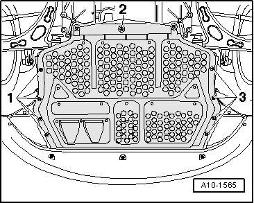
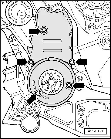
Bottom section of notched belt guard to cylinder block10 → Remark
Centre section of notched belt guard to cylinder block10 → Remark
Vibration damper to the crankshaft wheel10 + 90° → Remark → Remark
Engine support to cylinder block40 + 180° → Remark → Remark
Engine support to body40 + 90° → Remark → Remark
Connection to engine console/body20 + 90° → Remark → Remark
Pendulum support to sub-frame100 + 90° → Remark → Remark
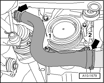
Front supercharger air tube to the engine block22

1)  45° is the equivalent of (1/8 turn)
2)  Fit with locking fluid; locking fluid → Electronic parts catalogue
3)  Renew bolts
4)  90° is the equivalent of (1/4 turn)
5)  180° is the equivalent of (1/2 turn)
   

Removing and installing cylinder head > < Toothed belt: removing and installing - vehicle ? 05.05 with small engine support