
Leon Mk1
|
| Consult the equivalence table for tools and equipment according to applicability among Seat / VW / Audi / Skoda → Chapter. |
| Special tools and workshop equipment required |
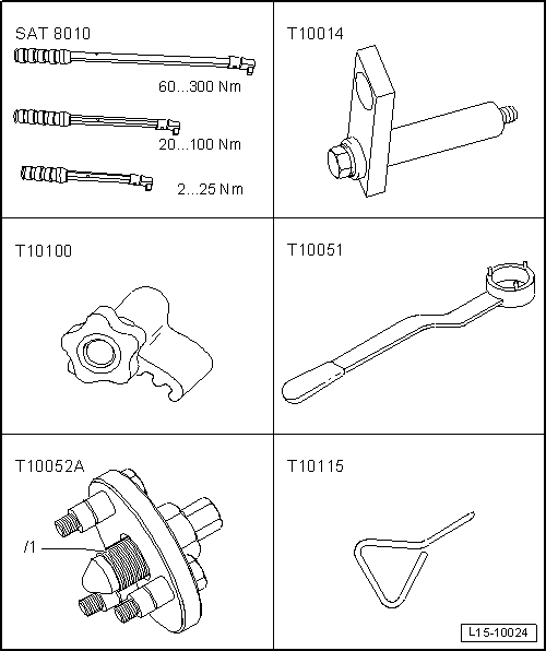
| t | Torque wrench kit -SAT 8010-, see equivalent → Anchor |
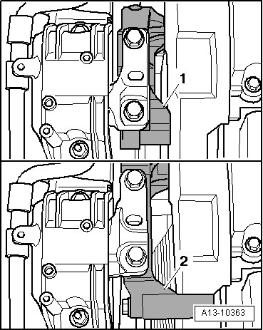
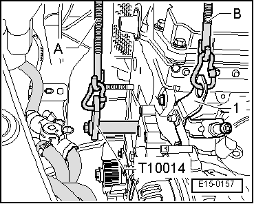
| t | Bracket -T10014- (only for vehicles ► 05.05 with small engine support), see equivalent → Anchor |
| t | counterhold -T10100-, see equivalent → Anchor |
| t | Hose clamp -T10051-, see equivalent → Anchor |
| t | Extractor -T10052A-, see equivalent → Anchor |
| t | Hose clamp -T10115-, see equivalent → Anchor |
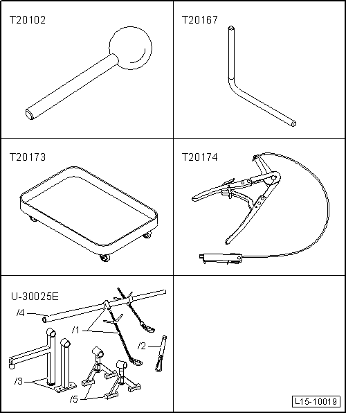
| t | Hose clamp -T20102-, see equivalent → Anchor |
| t | Hose clamp -T20167-, see equivalent → Anchor |
| t | Collecting tray -T20173-, see equivalent → Anchor |
| t | Base -T20174-, see equivalent → Anchor |
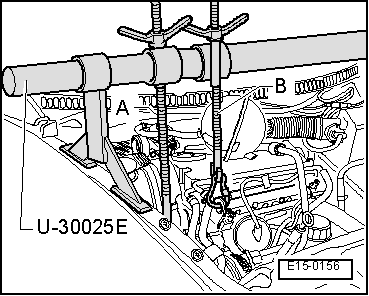
| t | Bracket -U 30025E- (only for vehicles ► 05.05 with small engine support), see equivalent → Anchor |
|
|
 Note
Note
|
|
Note
|
|
|
|
|
|
 WARNING
|
|
|
|
|
|
|
|
Note
|
|
|
|
Note
|
|
|
|
|
|
|
|
|
|
Note
|
|
Note
|
|
|
|
|
|
| stage: | Tighten | ||
| I |
| ||
| II |
| ||
| III |
| ||
| IV |
|
Note
|
|
|
|
|
Note
|
|
| Component | Nm | |
| Notched belt rear protection to cylinder head | 10 → Remark | |
| Hall sender to the cylinder head | 10 → Remark | |
| Pin to cylinder head | 15 | |
| Hub to the camshaft | 100 | |
| Oil pressure switch to oil filter bracket | 20 | |
| Oil supply pipe to the turbocharger | 22 | |
| Oil supply pipe to oil filter bracket | 22 | |
| Oil return pipe to the engine block | 30 | |
| Bracket | to turbocharger | 20 |
| Turbocharger | To engine block | 40 |
| Front air hose | To engine block | 15 |
| to bracket | 8 | |
|
| Component | Nm | ||
| Hall sender -G40- to the cylinder head | 10 → Remark | ||
| Notched belt rear protection to cylinder head | M6 | 10 → Remark | |
| M8 | 25 → Remark | ||
| Hub to the camshaft | 100 | ||
| Centre section of notched belt guard to cylinder block | 10 → Remark | ||
| Bottom section of notched belt guard to cylinder block | 10 → Remark | ||
| Exhaust gas recirculation radiator to intake manifold | 22 | ||
| Turbocharger support to | Turbocharger | 25 | |
| cylinder block | 60 | ||
| Oil return pipe to the turbocharger | 15 | ||
| Exhaust gas recirculation joint hose | exhaust gas recirculation radiator | 22 | |
| Exhaust manifold | 25 | ||
| Front crosspiece of the vehicle to the bodywork | 22 | ||
| Heat shield to cylinder block | 35 | ||
| Ribbed belt tensioner to ancillaries bracket | 23 | ||
| Guide tube for the dipstick to | Oil filter bracket | 10 | |
| Attachment ring | 10 | ||
| Support for the oil supply pipe | 10 | ||
| Oil supply pipe to oil filter bracket | 22 | ||
| Oil pressure switch to oil filter bracket | 20 | ||
| Right air hose to bracket | 8 | ||
|