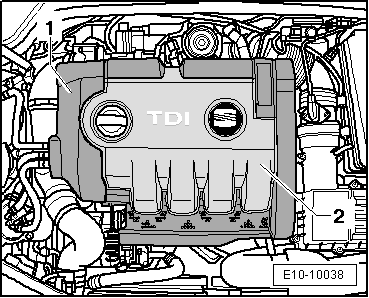
seat Workshop Repair Guides

SEAT Workshop Service and Repair Manuals

Sealing flanges and flywheel: Removing and installing. > < Pistons and conrods: dismantling and assembling
Removing and installing ancillary bracket
t  Removing → Anchor
t  Installing → Anchor
t  Tightening torques → Anchor
  Note
With the introduction of the engine support 06.05 ► it is necessary to use the support -U 30025E-
Consult the equivalence table for tools and equipment according to applicability among Seat / VW / Audi / Skoda → Chapter.
Special tools and workshop equipment required
t  Torque wrench kit -SAT 8010-, see equivalent → Anchor
   
t  counterhold -T10038-, see equivalent → Anchor
  W00-1005
t  Socket -U 30025E-, see equivalent → Anchor
Removing
  WARNING
Observe safety precautions when disconnecting the battery → Electrical system; Rep. gr.27.
–  Disconnect earth wire at battery with ignition switched off.
  W00-2961
Engine code letters BJB, BKC, BXE, BXF
–  Take out the oil dipstick -1- from its guide tube.
–  Lift the engine cover on one side -arrows 2- and remove it forwards -arrow 3-.
–  Replace the oil dipstick in the guide tube.
  E10-10002
–  Unscrew bolts -1- and -4-.
–  Remove the vacuum duct -2-.
–  Disconnect the electrical connection -3- from the supercharger pressure sender -G31-
–  Remove coolant hose -5- from the air ducts.
–  Pull the air duct upwards and place it about 10 centimetres from the left hand side of the vehicle.
  A21-0334
Select engine identification letters BLS
–  First remove the outer cover -1- and then the inner cover -2- upwards equally.
  E10-10038
–  Release the fuel and coolant hoses from their fittings on the air duct.
–  Remove bolt -1-.
–  Remove air duct by lifting retaining clips -arrows- slightly.
Continued for all vehicles
–  Remove poly V-belt → Chapter.
  A10-10266
–  Extract the fuel filter upwards -arrow-.
Only vehicles 06.05 ►
  Note
To secure the engine assembly with the support -U-30025E- this must be centred as much as possible with the symmetrical axis of the engine assembly.
  A10-1685
–  Position bracket -U-30025E- on bolted flange for wing panels.
–  Hang-in the snap hooks to the spindles on the lifting eyes.
–  Take up weight of engine with the spindles (do not raise).
  E13-10016
–  Unscrew the fixing bolts on the bracket for ancillary units
–  Raise the engine with the suspension tool -U-30025E- to extract the two upper bolts from the engine mount.
Continued for all vehicles
–  Remove Poly V-belt tension device.
  N13-0221
–  Unplug electrical connector -2-.
–  Unscrew electrical wiring -1- and clamp -3- and remove from alternator.
  A27-0218
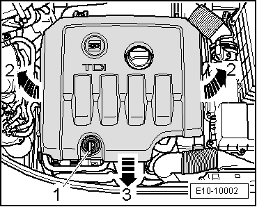
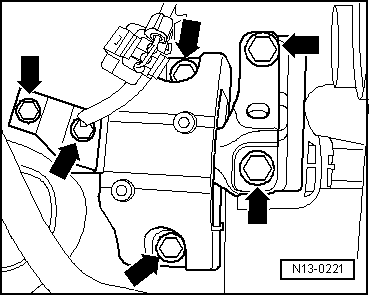
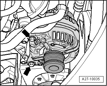
–  Screw out bolts -arrows- and remove alternator.
–  Remove alternator upwards.
  Note
t  
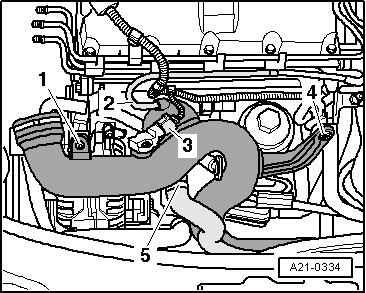
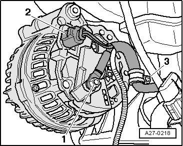
If the alternator is stuck on its support, tighten the fixing screw 2 turns less.
t  Carefully tap the bolt heads with the flat side of the hammer (in this manner you release the alternator fixing clamps).
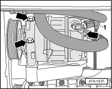
  WARNING
The air conditioning refrigerant circuit must not be opened.
  Note
To prevent damage to the air conditioning compressor and refrigerant pipes/hoses, ensure that the pipes and hoses are not stretched, kinked or bent.
  A27-10035
–  Disconnect electrical connection -1- for magnetic coupling on air conditioner compressor.
–  Remove compressor bolts -arrows-.
  A10-1637
–  Suspend the air conditioner compressor above with refrigerant hoses still connected, securing it with the securing tool -T10038- to the lock carrier plate. Take special care not to damage the system.
–  Remove the engine assembly lifting rings on the engine side.
  E10-10007
–  Remove the auxiliary bracket -bolts 1 … 6-.
Installing
Continue the installation in the reverse order of removal sequence, observing the following:
–  Check whether dowel sleeves for aligning the ancillaries bracket are fitted in cylinder block and install sleeves if necessary.
–  Tighten the screws in the sequence-1 … 6-.
–  Install the air conditioner compressor → air conditioning system ; Rep. gr.87.
–  Fit the alternator → Electrical system; Rep. gr.27.
–  Install Poly V-belt tension device.
–  Connect battery. Precautions → Electrical system; Rep. gr.27.
Tightening torques
  A13-0669
ComponentNm
Bracket for auxiliary units on engine block45
Idle wheel to bracket for the ancillaries40 + 90° → Remark → Remark

1)  Renew bolts
2)  90° is the equivalent of (1/4 turn)
   

Sealing flanges and flywheel: Removing and installing. > < Pistons and conrods: dismantling and assembling