| –
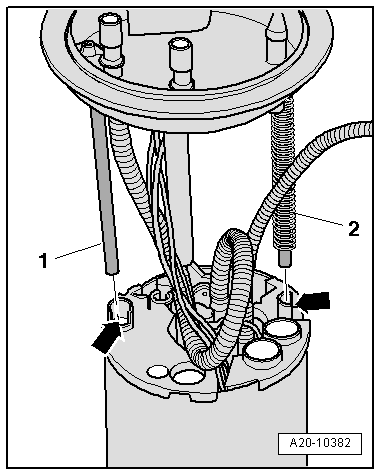
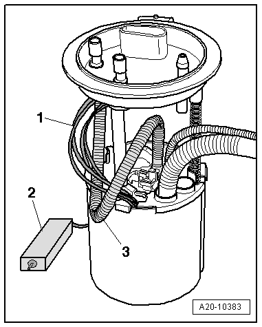
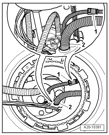
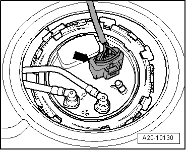
| Access through the fuel tank opening, separate the conduit -1- to the spray jet, for this press the clip to release it. |
| –
| Remove the fuel supply conduit -2- of the fuel supply unit. |
| –
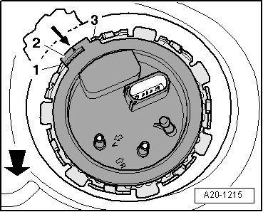
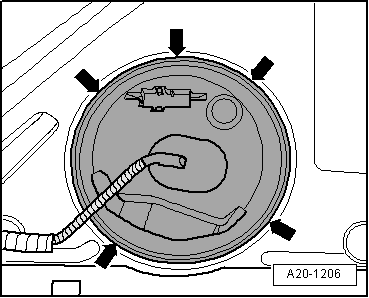
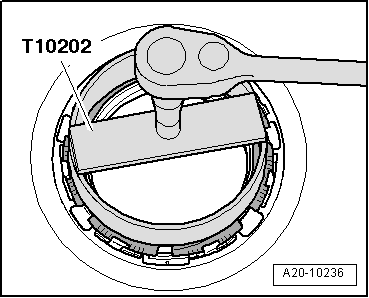
| Remove the fuel supply unit . |

Note | t
| When removing fuel delivery unit, make sure you do not bend float arm of fuel gauge sender -G-. |
| t
| Note that there is still fuel in the fuel delivery unit. |
| Installation is carried out in the reverse sequence; note the following: |
Note | t
| When inserting the fuel delivery unit ensure that the fuel gauge sender is not bent -G-. |
| t
| Check that the fuel hoses sit firmly. |
|
|
|

 WARNING
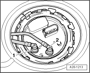
 Caution