
Leon Mk1
|
|
|
|
|
|

|
|
|
|
|
|
|
|
|
 Note
Note
|
|
|
|
|
|
|
|
|
|
Note
|
|
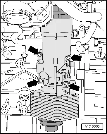
| Component | Nm | ||
| Oil filter bracket to cylinder block | 14 + 90° → Note → Note | ||
| Guide tube | Oil filter bracket | 10 | |
| Oil dipstick to | Attachment ring | 10 | |
| Cable harness bracket to oil filter bracket | 10 | ||
| Oil pressure switch to oil filter bracket | 20 | ||
|