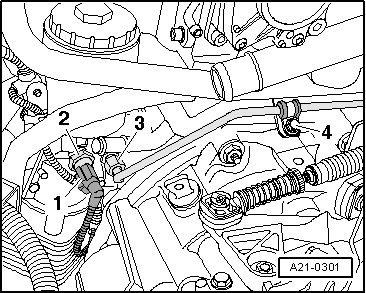
seat Workshop Repair Guides

SEAT Workshop Service and Repair Manuals

Ignition system, glow plug system > < Exhaust gas recirculation radiator: removing and fitting
Exhaust gas recirculation joint hose: removing and fitting
t  Removing → Anchor
t  Fitting → Anchor
Removing
   
–  Detach the outer -1- and inner -2- engine covers, by pulling them evenly upwards.
  E10-10038
–  Remove the air conduit cover by releasing the side tabs -arrows-.
  A10-10367
–  Unclip the air conduit in the lower part by releasing the tabs -arrows-.
–  Remove the lower section of the air duct together with the air hose.
  A10-10368
–  Separate the electrical connector -1- from the air mass gauge -G70-.
–  Uncouple the flexible air hose -3- and the flexible air conduit -2-.
–  Unscrew the bolt -4- and remove the air filter housing.
  A10-10369
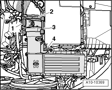
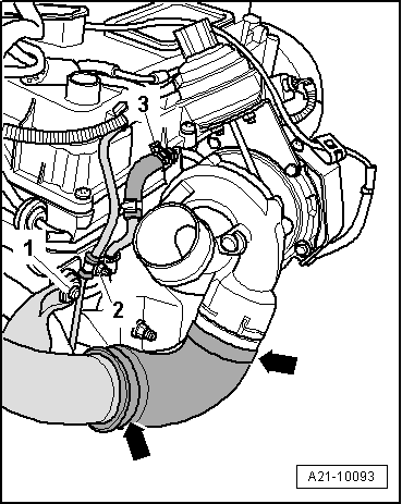
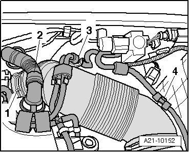
–  Detach the flexible tube -2- from the crankcase breather.
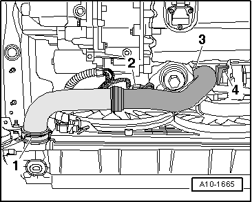
–  Remove the flexible air hose -4- and the pressure hoses -3- together with the air conduit flexible hose.
–  Loosen the clamp -1-.
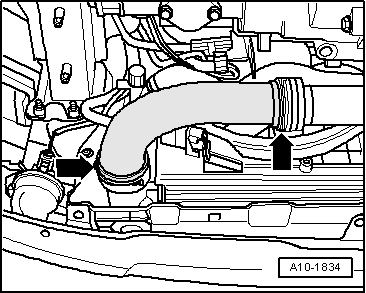
–  Turn back the flexible air conduction tube and detach it from the exhaust gas turbo compressor.
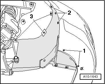
–  Remove the right front wheel.
  A21-10152
–  Remove centre noise insulation -mounting parts 1 ... 3-.
  A10-1565
–  Remove right soundproofing -Anchorage parts 1 ... 3-.
  A10-1643
–  Remove the left hand side air hose; to do this, lift the retaining clips slightly -arrows-.
  A10-1834
–  Pull the fastening tabs out a little -arrows- and remove the air hose.
–  Unscrew bolt -1-.
  A21-10093
–  Unscrew bolt -4-.
–  Disconnect the joint hose -3-.
  A10-1665
–  Remove the securing elements for the control cables from the selection and relay rods.
  A34-0620
–  Remove the control cable support from the gearbox and move to one side -arrows-.
  A34-0621
–  Separate the connector -1- of the oil pressure sender -F1-.
–  Remove the oil supply tube on the oil filter bracket -3- and on the liquid coolant tube -4-.
  A21-0301
–  Unscrew the bolts -1- in the connecting pipe for exhaust gas recirculation.
  A26-10406
–  Unscrew the bolt -arrow- (according to version).
  A15-0914
–  Unscrew bolts -3- and -4-.
–  Exhaust gas recirculation joint hose:
Fitting
–  Installation is carried out in the reverse order.
–  Fit the charge air system lines, follow the instructions during this → Chapter.
  A23-10151

Ignition system, glow plug system > < Exhaust gas recirculation radiator: removing and fitting