
Leon Mk1
|
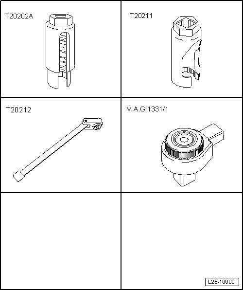
| Special tools and workshop equipment required |
| t | Socket wrench 22 mm -T20202A-, see equivalent → Anchor |
| t | Socket wrench 17 mm -T20211-, see equivalent → Anchor |
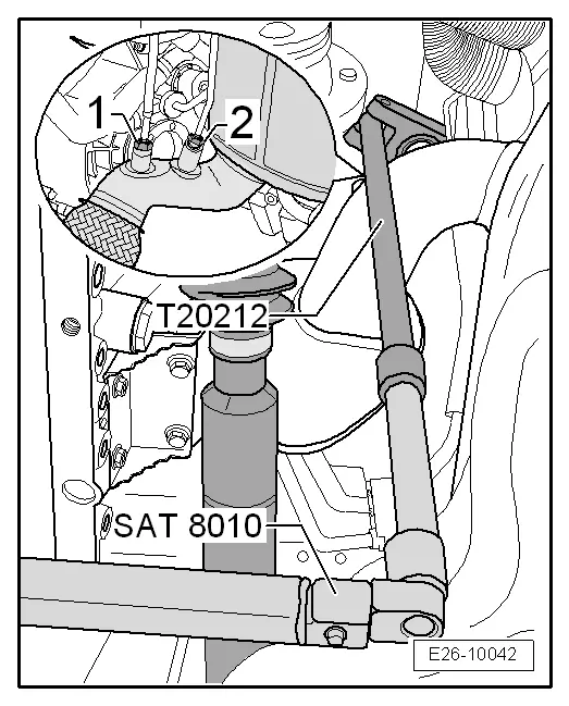
| t | Articulated wrench e/c 17 -T20212-, see equivalent → Anchor |
| t | "Ratchet 1/2"" x 9-12" -VAG 1331/1-, see equivalent → Anchor |
|
|
|
|
|
|
|
|
|
 Note
Note
|
|
Note
|
|
|
|
|
|
|
|
|
|
|
|
|
|
|
|
|
|
Note
|
|
|
|
|
|
|
|
|
|
Note
|
|
Note
|
|
|
|
|
|
|
|
|
|
|
|
|
|
|
|
|
|
|
|
Note
|
|
|
|
|
|
|
|
Note
Note
|
|
| Component | Nm | |||
| Exhaust gas recirculation radiator to engine block | 10 | |||
| Turbocharger oil backflow tubing | 15 | |||
| Turbocharger support to | Turbocharger | 25 | ||
| cylinder block | 60 | |||
| Exhaust gas recirculation joint hose | exhaust gas recirculation radiator | 22 | ||
| Exhaust manifold | 25 1) | |||
| Front crosspiece of the vehicle to the bodywork | 23 | |||
| Heat protection plate to the exhaust manifold | 25 1) | |||
| ||||