seat Workshop Repair Guides

SEAT Workshop Service and Repair Manuals

Components and functions > < Actuator diagnostic: operation
Injection commencement: verification and adjustment
   
Injection commencement: verification and adjustment
Special tools and workshop equipment required
t  Torque spanners -SAT 8010-
t  Adjustment tool -T20038-
t  Holding tool -T20102-
t  Graduated TDC setting tool -U-20010-

Verification process
–  Remove the flexible suction tube located between the air filter and the exhaust manifold.
–  Remove the upper protection cover of the notched belt.
   
–  Verification of the notched belt tension. The notch and the bump -arrows- should coincide.
If the marks do not coincide:
–  Adjust the notched belt tension → Rep. Gr.15
  N13-0166
–  Turn the crankshaft until the TDC point for cylinder 1 notch.
Engine removed from the vehicle:
  V23-0018
–  Fit the graduated TDC setting tool -U-20010- as shown in the diagram.
–  Calibrate the tool to 5 mm -arrow A-. The left notch of the vernier is the reference point.
–  Turn the crankshaft until the TDC of the engine flywheel coincides with the point on the adjustment apparatus -arrow B-.
  E13-0022
–  Ensure that the cogwheel of the injection pump can be secured using the -T20102- holding tool.
If the tool does not fit in the holes, the supply commencement needs to be adjusted as follows:
–  Remove the cylinder head cover.
  E23-0038
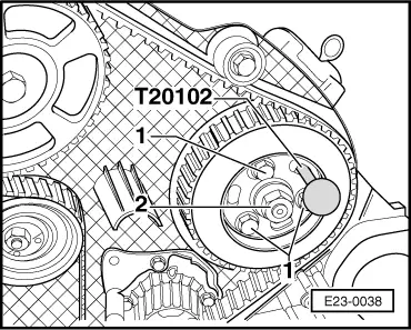
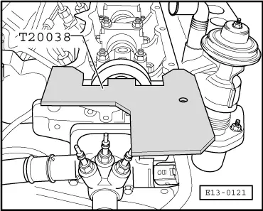
–  Immobilise the camshaft using the timing adjustment tool -T20038-.
Centre the adjustment tool as follows:
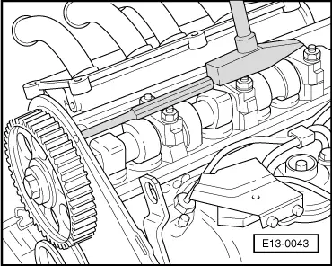
–  Once the camshaft has been immobilised, turn it until the end of the ruler stops at the cylinder head. Measure the resulting play on the other end of the ruler using a thickness gauge. Insert a gauge with the play reduced by half between the ruler and the cylinder head. Then, turn the camshaft so that the ruler presses on the gauge. Insert a second gauge with the same measurement on the other end between the ruler and the cylinder head.
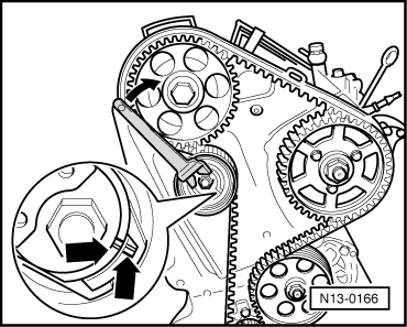
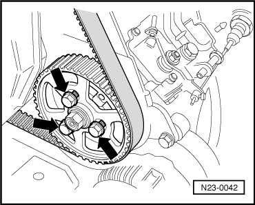
–  Loosen by a 1/2 turn the attachment bolt of the camshaft cogwheel.
  E13-0121
–  Pass a punch through the hole in the rear protection of the notched belt and remove the cogwheel from the camshaft cone by a knock with a hammer (to the punch).
  E13-0043
–  Loosen the attachment bolts -arrows- of the injection pump cogwheel.
–  Turn the hub until the injection pump cogwheel enters the pin.
–  Recheck the TDC mark on the engine flywheel.
Tighten the attachment bolt between the cogwheel and the camshaft.
   Tightening torque: 45 Nm
–  Tighten the attachment bolts of the injection pump cogwheel
   Tightening torque: 25 Nm
–  Remove the holding tool -T20102-.
–  Remove the adjustment tool -T20038- from the camshaft.
–  Turn the crankshaft in the normal rotation direction of the engine until arriving at the TDC point for cylinder 1.
  N23-0042
–  Ensure that the cogwheel of the injection pump can be secured using the -T20102- holding tool.
If the injection pump cogwheel cannot be immobilised using the tool:
–  Loosen the attachment bolts of the injection pump cogwheel.
–  Turn the hub until the injection pump cogwheel enters the tool.
–  Tighten the attachment bolts of the injection pump cogwheel.
   Tightening torque: 25 Nm
–  Fit the notched belt protection, the cylinder head cover and the flexible suction tube.
  E23-0038

Components and functions > < Actuator diagnostic: operation