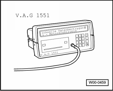
seat Workshop Repair Guides

SEAT Workshop Service and Repair Manuals

Fuel preparation system Diesel injection > < Fault memory: erasing
Actuator diagnostic: operation
Special tools and workshop equipment required
   
t  Fault reader -V.A.G 1551-
  W00-0459
t  -V.A.G 1551/3B- cable
  Note!
The equipment -V.A.G 1552- may be used instead of the -V.A.G 1551-, however in this case the results cannot be printed.
During the diagnostic, the actuators activate the following components in this order:
1 - Exhaust gas recirculation valve -N18-
2 - Indicator for preheat time -K29-
3 - Relay for glow plugs -J52-
4 - Full charge limit valve -N194-
5 - Injection commencement valve -N108-
6 - Idle acceleration valve -N177- (engines with air conditioning)
  Note!
t  The actuator diagnostic can be carried out with the engine running or not. As the noise of the valves themselves can be appreciated more when the engine is stopped, it is better to carry out the test with the engine stopped.
t  The diagnostic function work process of the actuation elements works using and activation signal followed by a deactivation signal. The message for each actuator appears twice.
t  The actuator activation is limited to 30 seconds, however it is possible to terminate at any moment by pressing the key .
t  Before carrying out the diagnostic of the actuators, the ignition must be disconnected.
Verification process
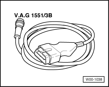
–  Connect the equipment -V.A.G 1551- (V.A.G 1552) and, using the corresponding “address code” 41, select the diesel pump electronic control unit. While doing this, the engine must be running idle → Chapter.
  W00-1038
Display indication:
–  Operate the fault reader taking into account the message displayed on the screen:
–  Press the keys 0 and 3 for the function “Actuator diagnostic”.
 
Rapid data transmission             HELP
Select the function XX                  
Display indication:
–  Confirm using the key Q
 
Rapid data transmission                Q
03 - Actuator diagnostics               
Display indication:
The valve should click.
  Note!
t  The clicking of the valve cannot be heard over the noise of the engine (when the engine is running) and can only be felt.
t  The movement of the exhaust gas recirculation valve piston can be clearly seen through the lateral rut.
If the valve does not click:
–  Test the exhaust gas recirculation valve -N18- → Rep. Gr.26
–  Press the key .
 
Actuator diagnostics                  ->
Exhaust gas recirculation valve N18     
Display indication:
The indicator should be on.
If the indicator is not turned on:
–  Verify the preheating indicator → Current flow diagrams, Electrical fault finding and Fitting locations
–  Press the key .
 
Actuator diagnostics                  ->
Indicator for preheat time K29          
Display indication:
The relay should click.
Due to the intensity of the current drawn by the glow plugs, the connection and disconnection of the relay will be obvious due to the increase and decrease of the internal lighting of the vehicle.
If the relay does not click:
–  Verify the glow plug relay → Current flow diagrams, Electrical fault finding and Fitting locations.
–  Press the key .
 
Actuator diagnostics                  ->
Relay for glow plugs J52                
Display indication:
The valve is activated and should click
  Note!
For this test, the voltage tester -V.A.G 1527B- can be connected to the full charge power cable. The indicator diode should be on.
–  Press the key .
 
Actuator diagnostics                  ->
Full charge limit valve N194-           
Display indication:
The valve activation is turned off, the diode indicator should also turn of and the click of the valve should be heard.
If the diode does not light:
–  Check cables and connections → Current flow diagrams, Electrical fault finding and Fitting locations.
–  Check the full charge limit valve → Chapter.
–  Press the key .
 
Actuator diagnostics                  ->
Full charge limit valve -N194           
Display indication:
When the valve is activated, the sound of the combustion changes perceptively (knocking).
If there is no perceptible change in the combustion sound:
–  Check the injection commencement valve -N108- → Chapter.
–  Press the key .
 
Actuator diagnostics                  ->
Injection commencement valve N108       
Display indication:
The valve is activated and should click once.
–  Press the key → Current flow diagrams, Electrical fault finding and Fitting locations.
 
Actuator diagnostics                  ->
Idle engine speed acceler. valve N177   
Display indication:
The valve is turned off and should click once more.
If the valve does not click:
–  Check the cables and connections according to the electric circuits schema.
–  Check the idle engine speed acceleration valve → Chapter.
–  Press the key .
 
Actuator diagnostics                  ->
Idle engine speed acceler. valve N177   
Display indication:
–  Press the keys 0 and 6 for the function “End data transmission”, confirm using the key Q.
–  Switch ignition off.
 
Rapid data transmission               ->
Select the function XX                  

Fuel preparation system Diesel injection > < Fault memory: erasing