seat Workshop Repair Guides

SEAT Workshop Service and Repair Manuals

Fuel filter: > < Removing and installing fuel gauge sender
Separating push-on couplings
Assignment of push-on couplings
  Note
t  The push-on couplings for fuel, vacuum and breather lines are colour coded. There is either a coloured dot on the connector or the release button is coloured.
t  Observe safety precautions → Chapter.
t  Observe rules for cleanliness → Chapter.
   
Plug-in connectorColour code on connector
Fuel supplyBlack
Fuel return lineBlue colour
BreatherWhite, beige
Vacuumgreen

  WARNING
Fuel supply line is pressurised. Wear eye protection and protective clothing to avoid eye injuries and skin contact. Before loosening hose connections, wrap a cloth around the connection. Then release pressure by carefully pulling hose off connection.
   
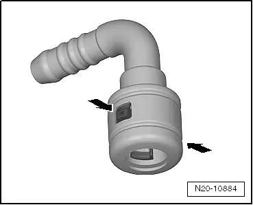
Version 1
Push-on coupling with release buttons -arrows- on right and left
  N20-10884
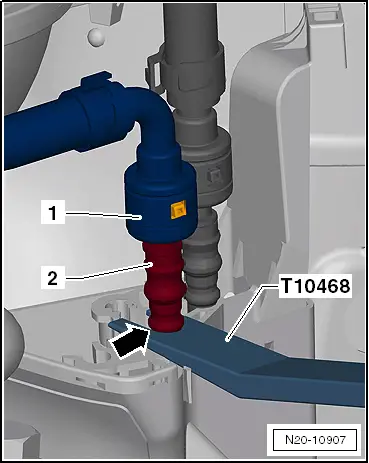
Opening
It is necessary to counterhold the separating point for fuel -1-.
–  Insert -T10468- between heat shield and stop -arrow- of fuel line -2- and counterhold.
  N20-10907
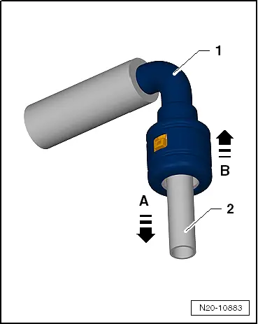
Continuation for all separating points of the fuel system.
–  Push push-on coupling -1- in -direction of arrow A-.
–  Press release buttons and pull push-on coupling -1- off fuel line -2- in -direction of arrow B-.
Take note of colour assignment during installation → Anchor
–  Ensure push-fit couplings are secured properly by pulling.
  N20-10883
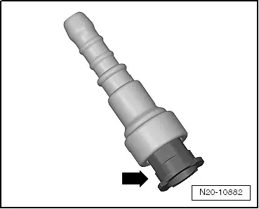
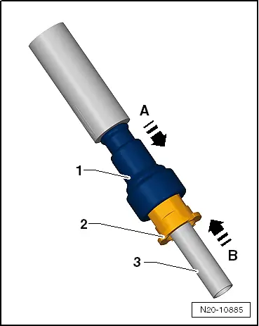
Version 2
Push-on coupling with pull-release mechanism -arrow-
  N20-10882
Opening
–  Push push-on coupling -1- in -direction of arrow A-.
–  Pull pull-release mechanism -2- in -direction of arrow B-.
–  Pull push-on coupling -1- off fuel line -3- in -direction of arrow B-.
Take note of colour assignment during installation → Anchor
–  Ensure push-fit couplings are secured properly by pulling.
  N20-10885
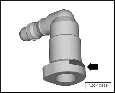
Version 3
Push-on coupling with front button -arrow-
Opening
–  Press release button -arrow- and pull push-on connectors off.
Take note of colour assignment during installation → Anchor
–  Ensure push-fit couplings are secured properly by pulling.
  N20-10898
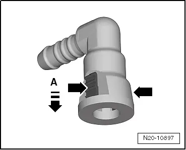
Version 4
Push-on coupling with release buttons -arrows- on right and left
Opening
–  Press push-on coupling in -direction of arrow A-.
–  Press release buttons -arrows- and pull push-on coupling off.
Take note of colour assignment during installation → Anchor
–  Ensure push-fit couplings are secured properly by pulling.
  N20-10897
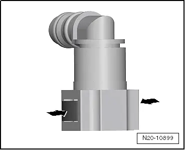
Version 5
Push-on coupling with release buttons -arrows- on right and left
Opening
–  Press release buttons -arrows- and pull push-on coupling off.
Take note of colour assignment during installation → Anchor.
–  Ensure push-fit couplings are secured properly by pulling.
  N20-10899
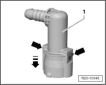
Version 6
Push-on coupling with release buttons -arrows- on right and left
Opening
–  Push push-on coupling -1- in -direction of the arrow- and maintain pressure.
–  Press release buttons -arrows- and pull push-on coupling off.
Take note of colour assignment during installation → Anchor.
–  Ensure push-fit couplings are secured properly by pulling.
  N20-10946

Fuel filter: > < Removing and installing fuel gauge sender