
Leon Mk1
| Piston and connecting rod disassemble and assemble |
| Engine code letters AEX |
| Engine code letters AER → Anchor |

| 1 - | Piston rings |
| q | Push in 120° |
| q | Disassemble and assemble with pliers for piston rings |
| q | Manually disassemble and assemble with great care the lubrication rings made up of three parts |
| q | Mark “TOP” at the bottom of the piston |
| q | Check the impact play → Fig. |
| q | Check the height play → Fig. |
| 2 - | Piston |
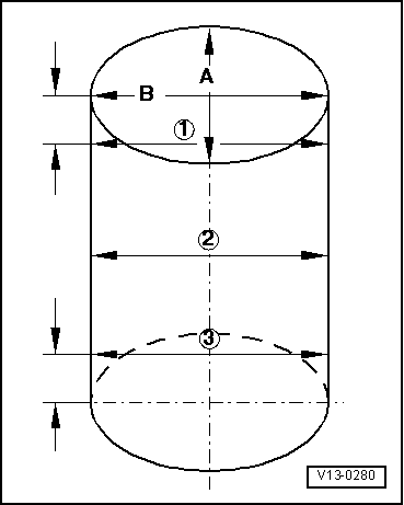
| q | Check → Fig. |
| q | Mark the assembly position and the belonging to the cylinder |
| q | The arrow at the bottom of the piston indicates the side of the pulley |
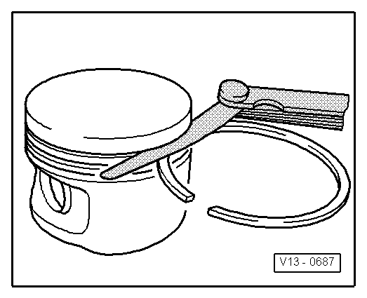
| q | Assemble with the tensing strap for the piston ring |
| 3 - | Piston pin |
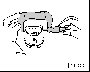
| q | Heat the piston to 60 °C in case of hard movement |
| q | Disassemble and assemble with -U-40077- |
| 4 - | Safety ring |
| 5 - | Connecting rod |
| q | Only replace by batches |
| q | Mark the belonging to the cylinder -A- |
| q | Assembly position: The -B- marks indicate the pulley |
| q | Axial guide for the piston |
| 6 - | Bearing casing |
| q | Insert the bearing casing and centre it |
| q | Do not confuse the bearing casings that were in use |
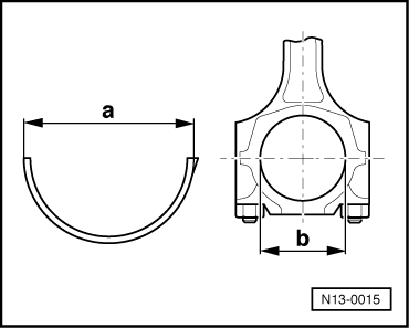
| q | Measure the initial tension → Fig. |
| q | Measure the radial play with plastigage: New: 0.020...0.061 mm Wear limit: 0.091 mm Do not turn the crankshaft when the radial play is measured |
| 7 - | Cylinder block |
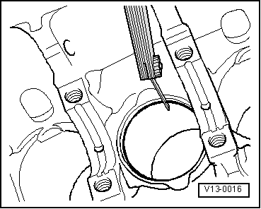
| q | Check the cylinder hole → Fig. |
| q | Piston an cylinder dimensions → Chapter |
| 8 - | Connecting rod cover |
| q | Remember the assembly position |
| q | If the connecting rods are fractured (cracked), the cover only fits in one position and only on the corresponding connecting rod |
| 9 - | Connecting rod bolt M8: 30 Nm + turn 1/4 (90°) rotation more M7: 20 Nm + turn 1/4 (90°) rotation more |
| q | Replace |
| q | Lubricate the thread and the surface |
| q | To measure the radial play, tighten with 20 or 30 Nm, but without continuing to turn |
|

| 1 - | Safety ring |
| 2 - | Piston pin |
| q | Heat the piston to 60 °C in case of hard movement |
| q | Disassemble and assemble with -U-40077- |
| 3 - | Piston |
| q | Check → Fig. |
| q | Mark the assembly position and the belonging to the cylinder |
| q | The arrow at the bottom of the piston indicates the side of the pulley |
| q | Assemble with the tensing strap for the piston ring |
| 4 - | Piston rings |
| q | Push in 120° |
| q | Disassemble and assemble the compression rings with the piston ring pliers |
| q | Manually disassemble and assemble with great care the lubrication rings made up of three parts |
| t | Mark “TOP” at the bottom of the piston |
| t | Check the impact play → Fig. |
| t | Check the height play → Fig. |
| 5 - | Connecting rod |
| q | Only replace by batches |
| q | Mark the belonging to the cylinder -A- |
| q | Assembly position: The -B- marks indicate the pulley |
| q | Axial guide for the piston |
| 6 - | Connecting rod cover |
| q | If the connecting rods are fractured (cracked), the cover only fits in one position and only on the corresponding connecting rod |
| 7 - | Connecting rod bolt, 20 Nm + turn 1/4 (90°) rotation more |
| q | Replace |
| q | Lubricate the thread and the surface |
| q | To measure the radial play, tighten with 20 Nm , but without continuing to turn |
| 8 - | Cylinder block |
| q | Check the cylinder hole → Fig. |
| q | Piston an cylinder dimensions → Chapter |
| 9 - | Bearing casing |
| q | Do not confuse the bearing casings that were in use |
| q | Measure the initial tension → Fig. |
| q | Insert the bearing casing and centre it |
| q | Measure the radial play with plastigage: New: 0.020...0.061 mm Wear limit: 0.091 mm Do not turn the crankshaft when the radial play is measured |
|
|
| Piston ring | Wear limit |
| Compression rings | 1.0 mm |
| Lubrication ring consisting of one part consisting of three parts | 1.0 mm -- → Note |
|
|
|
| Piston ring | Wear limit |
| Compression rings | 0.15 mm |
| Lubrication ring consisting of one part | 0.15 mm |
| Consisting of three parts | not measurable |
 Note!
Note!
|
|
|
|