seat Workshop Repair Guides

SEAT Workshop Service and Repair Manuals

Actuator diagnostic > < Hall sender G40 : verification
Fault reader: consulting and erasing the fault memory
Special tools and workshop equipment required
   
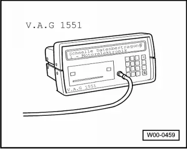
t  Fault reader -V.A.G 1551- (or vehicle system tester -V.A.G 1552-) with cable -V.A.G 1551/3B-
Operation sequence
–  Connect fault reader -V.A.G 1551- (-V.A.G 1552-) and select engine electronics control unit with the “Address code” 01. While connecting, the engine should be idling. Fault reader: Connecting and selecting the engine electronics control unit → Chapter.
In the case where the engine will not start:
–  Turn the ignition on.
–  Activate the fault reader printer by pressing the key Print. The indicator light of the switch should light.
  W00-0459
Display indication:
–  Operate the fault reader taking into account the message displayed on the screen:
–  Select the operation mode 1 “Rapid data transmission”.
–  Press keys 0 and 1 for the “Engine electronics” function and confirm input with the “Q” key.
–  Press the key .
 
Rapid data transmission             HELP
Select the function XX                  
Display indication:
–  Press the keys 0 and 2 for the function “Consult fault memory”, confirm using the key Q.
 
Rapid data transmission             HELP
Select the function XX                  
The display should read “No fault detected”.
If one or more faults are stored
The recorded faults are displayed and printed one after the other.
 
X faults detected                       
When printing is finished the following is displayed:
–  Press the keys 0 and 5 for the function “Erase fault memory”, confirm using the key Q.
  Note
The fault memory will not be erased if the ignition is turned off between the “Read fault memory” and “Erase fault memory” functions.
 
Rapid data transmission             HELP
Select the function XX                  
Display indication:
–  Press the key .
 
Rapid data transmission               ->
The fault memory is erased              
Display indication:
–  Press keys 0 and 6 for the “End output” function and confirm input with the Q key.
–  Eliminate the faults that have been displayed using the corresponding fault reference table → Chapter
Automatic verification cycle
When carrying out assembly and verification work, the other control units may detect anomalies such as disconnections. For this reason, once the work on the vehicle is finished all of the control unit fault memories must be read and then erased in the following manner:
–  Press twice the key 0 for the address code “Automatic verification” and confirm using the Q key. The equipment -V.A.G 1551- will emit all known address codes.
If a control unit responds to its identification, the amount of faults or the message “no fault detected” will be displayed.
All of the faults that may have been recorded by the system are displayed and printed successively. Then, the -V.A.G 1551- will emit the following address code.
 
Rapid data transmission             HELP
Select the function XX                  
The automatic verification is finished when the following indication is displayed:
 
V.A.G- SELF DIAGNOSIS               HELP
1 - Rapid data transfer                 
or
appear alternating
–  Erase all of the fault memories and, then, carry out a test run.
–  During the road test the following operating conditions must be fulfilled:
l  The coolant temperature should be above 80 °C.
l  When this temperature is reached, the service stages must be reached several times
t  Idling
t  Part throttle
t  Full throttle
t  Overrun mode
l  For acceleration, the engine speed should be at more than 3.500 rpm.
–  Following the test, re-consult the fault memories using the “Automatic verification cycle”.
If no fault is stored
–  Press the key .
 
V.A.G- SELF DIAGNOSIS               HELP
2 - Flash code output                   
Display indication:
–  Press keys 0 and 6 for the “End output” function and confirm input with the Q key.
–  Disconnect the ignition.
 
Rapid data transmission             HELP
Select the function XX                  

Actuator diagnostic > < Hall sender G40 : verification