seat Workshop Repair Guides

SEAT Workshop Service and Repair Manuals

Fault table: codes P0 SAE > < Fault memory
Conformity code: generating
Special tools and workshop equipment required
   
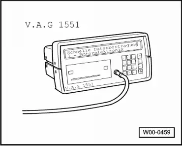
t  Fault reader -V.A.G 1551- or Vehicle systems checker -V.A.G 1552- with Lead -V.A.G 1551/3B-
Test conditions
  W00-0459
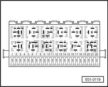
l  Fuses 15 and 18, OK.
l  Vehicle stopped.
l  All electrical consumers, for example lights and heated rear window, must be off.
l  On vehicles with air conditioner, the AC must be off.
l  Exhaust system, airtight between the catalyst and cylinder head.
l  Coolant temperature, 80 °C minimum → .
l  Intake air temperature below 60 °C → .
Work sequence
–  Connect the -V.A.G 1551- (V.A.G. 1552). Switch on the ignition and enter “address code” 01 to select the engine control unit. (Fault reader: Connecting and selecting the engine control unit → Chapter.).
Operation 1: consult the fault memory
  E01-0119
The display reads:
–  Press 0 and 2 for the function “Consult fault memory” and press Q to confirm the entry.
 
Rapid data transmission             HELP
Select function XX                      
The display shows the number of faults stored or “No fault found”.
If a fault is stored:
–  Eliminate faults on the print out, using the fault table: Codes P0 SAE → Chapter, Codes P1 SAE → Chapter.
If no fault is stored:
–  Press .
Operation 2: clear the fault memory
 
X faults found                          
The display reads:
–  Press 0 and 5 for the function “Clear fault memory” and press Q to confirm the entry.
  Note!
The conformity code returns to zero or is cleared each time the fault memory is cleared.
 
Rapid data transmission             HELP
Select function XX                      
The display reads:
  Note!
The fault memory will not clear if the ignition is switched off between consulting and clearing the fault memory.
–  Press .
Operation 3: Adapt the throttle valve drive unit to the engine control unit
 
Rapid data transmission               ->
The fault memory is clear               
The display reads:
–  Press 0 and 4 for the function “Start basic settings” and press Q to confirm the entry.
 
Rapid data transmission             HELP
Select function XX                      
The display reads:
–  Press 0, 6 and 0 for “Display group number 60” and press Q to confirm the entry.
 
Basic settings                      HELP
Enter display group number XXX          
The display reads: (1...4 = display fields)
–  Check the target values in display fields 3 and 4: Display field 3: 0...8 Display field 4: ADP. ON, ADP. OK
 
Basic settings  60                    ->
      xx %      xx %      x      ADP. ON
The display reads: (1...4 = display fields)
–  After at least 30 seconds, end the adaptation by pressing .
If the described message does not appear:
–  Test the throttle valve drive unit → Chapter.
If the described message appears:
–  Start the engine and let it idle.
Operation 4: lambda probe ageing diagnosis (period monitoring)
 
Basic settings  60                    ->
      xx %      xx %      8     ADP. OK 
The display reads:
–  Press 0 and 8 for the function “Read measurement value block” and press Q to confirm the entry.
 
Rapid data transmission             HELP
Select function XX                      
The display reads:
–  Press 0, 3 and 0 for “Display group number 30” and press Q to confirm the entry.
 
Read measurement value block        HELP
Enter display group number XXX          
The display reads: (1...2 = display fields)
–  Test the operative state of the pre-catalyst lambda regulation (display field 1): Target value: 1 1 1 (Meaning → )
–  Test the operative state of the post-catalyst lambda regulation (display field 2): Target value: 1 1 0 (Meaning → )
  Note!
t  The first position of the 3-digit numerical block switches temporarily between 0 and 1 (lambda probe heating ON and OFF).
t  Depending on the state of lambda regulation, the 3-digit numerical may alternate between 0 and 1.
t  The bits in the display field 1 and 2 hold at 1 when the catalyst temperature is above 400.0 °C ( → Anchor).
t  The 3rd bit in display field 2 only changes to 1 when the engine is running at half load (2500-4000 rpm).
If the target values are not reached:
–  Consult the fault memory → Chapter.
If the target values are reached:
–  Press .
 
Read measurement value block 30       ->
                   1                   2
The display reads:
–  Press 0 and 4 for the function “Start basic settings” and press Q to confirm the entry.
 
Rapid data transmission             HELP
Select function XX                      
The display reads:
–  Press 0, 3 and 4 for “Display group number 34” and press Q to confirm the entry.
 
Basic settings                      HELP
Enter display group number XXX          
The display reads: (1...4 = display fields)
–  Let the engine run at high revs until display field 4 changes from “Test OFF” to “Test ON”. The catalyst temperature in display field 2 must reach at least 400 °C.
  Note!
This process may take a few minutes.
–  Check the amplitude ratio in display field 3: Target value: 0.7... 2.00
–  Let the engine run at high revs until display field 4 shows the target value “F1-S1 OK”.
If the described message does not appear:
–  Consult the fault memory → Chapter.
If the described message appears:
–  Press C. Engine revs drop to idling revs.
 
System in basic settings  34          ->
         1         2         3         4
The display reads:
–  Press 0, 3 and 6 for “Display group number 36” and press Q to confirm the entry.
 
Basic settings                      HELP
Enter display group number XXX          
The display reads: (1...4 = display fields)
–  Depress the brake pedal and hold it down. The engine control unit raises engine revs to 1200...1400 rpm approx.
–  Let the engine run at high revs until display field 2 changes from “Test OFF” to “Test ON”.
  Note!
This process may take a few minutes.
–  Let the engine run at high revs until display field 2 shows the target value “F1-S2 OK”.
If the described message does not appear:
–  Consult the fault memory → Chapter.
If the described message appears:
–  Press C. Engine revs drop to idling revs.
Operation 5: lambda regulation system diagnostic
 
System in basic settings  36          ->
                   1                   2
The display reads:
–  Press 0, 3 and 7 for “Display group number 37” and press Q to confirm the entry.
 
Basic settings                      HELP
Enter display group number XXX          
The display reads: (1...4 = display fields)
–  Depress the brake pedal and hold it down. The engine control unit raises engine revs to 1200...1400 rpm approx.
–  Let the engine run at high revs until display field 4 shows the target value “Syst. OK”.
If the described message does not appear:
–  Consult the fault memory → Chapter.
If the described message appears:
–  Press . Engine revs drop to idling revs.
 
System in basic settings 37           ->
         1         2         3         4
The display reads:
–  Press 0, 4 and 3 for “Display group number 43” and press Q to confirm the entry.
 
Basic settings                      HELP
Enter display group number XXX          
The display reads: (1...4 = display fields)
–  Depress the brake pedal and hold it down. The engine control unit raises engine revs to 1200...1400 rpm approx.
–  Let the engine run at high revs until display field 4 shows the target value “F1-S2 OK”. The catalyst temperature in display field 2 must reach at least400 °C.
If the described message does not appear:
–  Consult the fault memory → Chapter.
If the described message appears:
–  Press Engine revs drop to idling revs.
Operation 6: catalyst diagnostic
  Note!
This diagnostic ends only after the lambda probe ageing diagnosis has been carried out successfully.
 
System in basic settings 43           ->
         1         2         3         4
The display reads:
–  Press 0, 4 and 6 for “Display group number 46” and press Q to confirm the entry.
 
Basic settings                      HELP
Enter display group number XXX          
The display reads: (1...4 = display fields)
–  Depress the brake pedal and hold it down. The engine control unit raises engine revs to 1200...1400 rpm approx.
–  Let the engine run at high revs until display field 4 changes from “Test OFF” to “Test ON”. The catalyst temperature in display field 2 must reach at least 400 °C.
–  Check the amplitude ratio in display field 3: Target value: 0.50 max.
–  Let the engine run at high revs until display field 4 shows the target value “Cat F1 OK”.
If the described message does not appear:
–  Consult the fault memory → Chapter.
If the described message appears:
–  Press C. Engine revs drop to idling revs.
Operation 7: diagnostic of the activated charcoal filter system (tank deaeration system)
  Note!
Do not shut off the engine during the following operations.
 
System in basic settings  46       ->   
         1         2         3         4
The display reads:
–  Press 0, 7 and 0 for “Display group number 70” and press Q to confirm the entry.
 
Basic settings                      HELP
Enter display group number XXX          
The display reads: (1...4 = display fields)
  Note!
During this diagnostic there should be no request from the engine, since, if so, it will be interrupted and you will have to accelerate to start again.
When the engine control unit starts the diagnostic, the message in field 4 changes from “Test OFF” to “Test ON”.
–  Let the engine idle until display field 4 shows the target value “VDD OK”.
If the described message does not appear:
–  Consult the fault memory → Chapter.
If the described message appears:
–  Press .
–  Consult the conformity code → Chapter.
 
System in basic settings 70        ->   
         1         2         3         4

Fault table: codes P0 SAE > < Fault memory