seat Workshop Repair Guides

SEAT Workshop Service and Repair Manuals

Fuel preparation system Diesel injection > < Fault memory: interrogating
Final control diagnosis: carrying out
Special tools and workshop equipment required
   
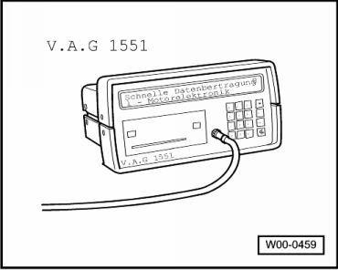
t  Fault reader -V.A.G 1551-
  W00-0459
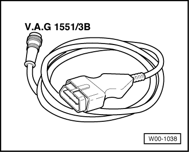
t  Cable -V.A.G 1551/3B-
  Note!
The vehicle system tester -V.A.G 1552- can be used instead of the fault reader -V.A.G 1551-, although a printout will not be possible in such cases.
Test requirements for vehicles with air conditioning system
l  Vehicle at room temperature (warmer than + 15 °C)
l  Air conditioning system switched on
l  Select lowest temperature and highest blower speed
The final control diagnosis activates the following components in the stated sequence:
1. Injection start valve -N108-
2. Exhaust gas recirculation valve -N18-
3. Air conditioner compressor intervention
4. Throttle valve positioner -V60-
5. Fuel cut-off valve -N109-
6. Relay for preheating elements -J52-
7. Preheating time warning light -K29-
8. Relay for low heating power -J356-
9. Relay for high heating power -J360-
  Note!
t  The activation of the different final controls is limited to 30 s, but it can be terminated at any moment by pressing key .
t  Before repeating the final control diagnosis, the ignition has to be disconnected.
Test sequence
–  Connect fault reader -V.A.G 1551- (V.A.G 1552) and select engine electronics control unit with the “address code” 01. When doing so the engine must be idling. (Fault reader: Connecting and selecting the engine electronics control unit → Chapter.)
  W00-1038
Indicated on display:
–  Operate the fault reader taking into account the information on the display:
–  Press keys 0 and 3 for the function “Final control diagnosis”.
 
Rapid data transfer                 HELP
Select function XX                      
Indicated on display:
–  Confirm entry with the Q key.
 
Rapid data transfer                    Q
03 -Final control diagnosis             
Indicated on display:
On activating the valve, the combustion noise clearly changes (knocking)
If you do not notice any change in the combustion noise:
–  Check the injection start valve -N108- → Chapter.
–  Press the key.
 
Final control diagnosis               ->
Injection start valve N108              
Indicated on display:
The valve should click
  Note!
t  The valve click cannot be heard due to the engine noise and it can only be felt.
t  The movement of the piston of the exhaust gas recirculation mechanical valve can be clearly seen by means of the lateral groove.
If the valve does not click:
–  Check exhaust gas recirculation valve -N18-: → Motor Mechanik; Rep. Gr.26.
–  Press the key.
 
Final control diagnosis               ->
EGR valveN18                            
Indicated on display:
Check the disconnection of the air conditioner compressor
The test will also appear in the case of a vehicle without air conditioner
The air conditioner compressor should stop in about 5 seconds (visual check), and then start and stop every 5 seconds
If the air conditioner compressor does not disactivate: → Current flow diagrams, Electrical fault finding and Fitting locations.
–  Press the key.
 
Final control diagnosis               ->
Intervention of air conditioner compress
Indicated on display:
The solenoid valve should click
  Note!
It is difficult to hear this clicking and it is better detected by touching it
If the valve does not click:
–  Check the throttle valve positioner -V60- → Chapter.
–  Press the key.
 
Final control diagnosis               ->
Throttle valve positioner V60           
Indicated on display:
The engine should stop
If the engine does not stop:
–  Switch ignition off.
–  Extract the fuel cut-off valve and clean off possible metal particles or dirt.
–  Repeat the final control disagnosis. If the engine does not stop again, replace the fuel cut-off valve → Item.
–  Stellglieddiagnose bei abgeschalteten Motor und eingeschalteter Zündung fortführen.
–  Press the key.
 
Final control diagnosis               ->
Fuel cut-off valve N109                 
Indicated on display:
The relay should click
Due to the high level of current absorbtion by the preheating elements, the connection and disconnection of the relay can also be noticed by the dimming and brightening of the interior lights
If the relay does not click:
–  Check the preheating elements relay: → Current flow diagrams, Electrical fault finding and Fitting locations.
–  Press the key.
 
Final control diagnosis               ->
Relay for preheating elements J52       
Indicated on display:
The warning light must flicker
If warning light does not flicker:
–  Checking preheating warning lamp: → Current flow diagrams, Electrical fault finding and Fitting locations.
–  Press the key.
  Note!
The two final controls that appear next are exclusively for vehicles that have heating for liquid coolant. Although they are two control relays, they are physically integrated in a capsule which cannot be dismantled.
 
Final control diagnosis               ->
Preheating time warning light K29       
Indicated on display:
The relay should click
If the relay does not click:
–  Check relay for low heating power: → Current flow diagrams, Electrical fault finding and Fitting locations.
–  Press the key.
 
Final control diagnosis               ->
Relay for low heating power J359        
Indicated on display:
The relay should click
If the relay does not click:
–  Check relay for high heating power: → Current flow diagrams, Electrical fault finding and Fitting locations.
–  Press the key.
 
Final control diagnosis               ->
High temperature relayJ360              
Indicated on display:
–  Press keys 0 and 6 for the “End data transfer” function and confirm input with the Q key.
–  Switch ignition off.
 
Rapid data transfer                 HELP
Select function XX                      

Fuel preparation system Diesel injection > < Fault memory: interrogating