SEAT Workshop Service and Repair Manuals
HOME
FEATURES
MENU
INDEX
ABOUT US
Track control link >
< Assembly overview for the VL107 constant velocity slip joint
Leon Mk1
Running gear
Running gear, axles, steering
Front suspension, drive shafts
Tripod type joint AAR?3300?i: Disassembling and assembling
Dismantling triple roller joint AAR 3300 i
Dismantling triple roller joint AAR 3300 i
Removing:
–
Clamp the drive shaft horizontally in the vice
Note
t
Always use protective jaws in the vice when clamping!
t
Take care not to damage drive shaft.
–
Mark the location of the joint body to the drive shaft.
If the parts are not marked and installed in their previous positions when assembled, noises develop during may subsequent vehicle operation.
Use a waterproof felt-tip pen for marking.
–
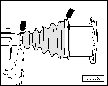
Open hose clips
-arrows-
.
–
Push back bellows.
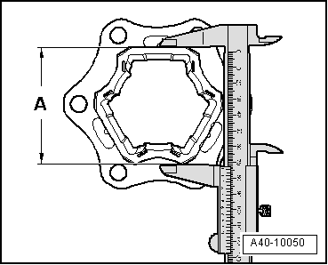
Distinguishing features of drive shafts AAR 2600 i and AAR 3300 i
–
Measure dimension
-A-
as shown.
t
Dimension
-A-
74 mm = drive shaft AAR 2600 i
t
Dimension
-A-
77 mm = drive shaft AAR 3300 i
Caution
It is important to use the correct special tools for the different drive shafts.
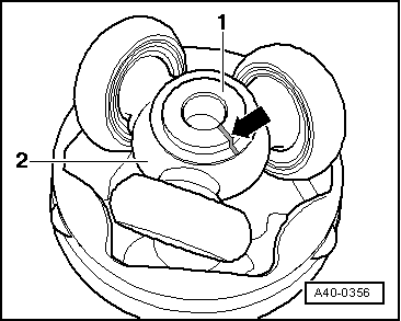
–
Apply removal and assembly tool -T40018- for triple roller joint AAR 3300 i (or removal and assembly tool -T40084- for triple roller joint AAR 2600 i) behind joint body.
The guide bolt
-1-
must rest against the outer joint body.
–
Bring removal and assembly tool into contact with joint body by turning knurled screws
-2-
.
Note
t
Joint body must be fixed in removal and assembly tool -T40018- or -T40084- without play.
t
Tighten the bolts
-2-
only by hand.
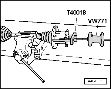
–
Screw multi-purpose tool - VW 771- into removal and assembly tool -T40018- or -T40084 -.
The illustration shows removal and assembly tool -T40018- for drive shaft AAR 3300 i.
When working on drive shaft AAR 2600 i use removal and assembly tool -T40084 -.
–
Remove joint body by knocking horizontally.
Leave joint body clamped in removal and assembly tool -T40018- or -T40084 -.
–
Mark positions of parts 1 and 2 in relation to each other before dismantling.
If the parts are not marked and installed in their previous positions when assembled, noises develop during may subsequent vehicle operation.
Use a waterproof felt-tip pen for marking.
1 -
Drive shaft
2 -
Triple roller spider
–
Remove grease with a lint-free cloth.
–
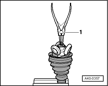
Remove the safety ring.
1 -
Circlip pliers (normal commercial type)
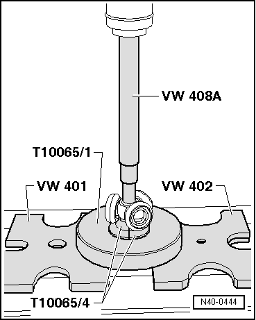
–
Press out the tripod star from the drive shaft
The assembly fixture -T10065/4- must not rest on the rolling body.
–
Pull off boot.
–
Remove grease from the shaft splines
–
Check rollers and roller races for wear.
–
Clean drive shaft and housing.
Running gear
Running gear, axles, steering
Front suspension, drive shafts
Tripod type joint AAR?3300?i: Disassembling and assembling
Track control link >
< Assembly overview for the VL107 constant velocity slip joint
 Caution
 Note
Note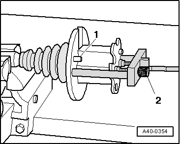
 Note
Note