
Leon Mk1
| Removing and installing wheel bearing housing |

| Special tools and workshop equipment required |
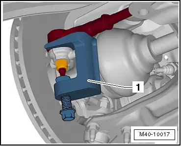
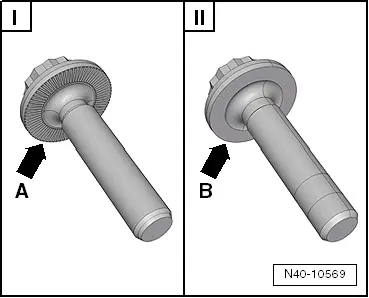
| t | Ball joint puller -3287A- |
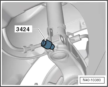
| t | Spreader -3424- |
| t | Ball joint puller -T10187- |
| t | Torque wrench -V.A.G 1332- |
| t | Engine/gearbox jack -V.A.G 1383 A- |
| t | Angle wrench -V.A.G 1756- |
|
 Caution
|
|
|
|
|
|
 Note
Note
|
|
|
|
| Specified torques |
| Component | Tightening torque | ||
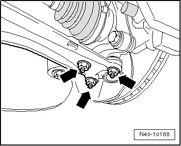
Suspension strut to wheel bearing housing
| 70 Nm + 90° | ||
Swivel joint to cast steel suspension link
| 60 Nm | ||
Swivel joint to sheet steel or forged aluminium suspension link
| 100 Nm | ||
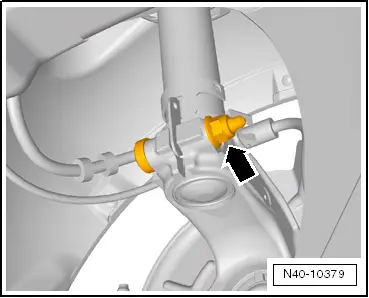
Track rod ball joint to wheel bearing housing
| Tighten to 100 Nm, then loosen (turn back) 180° and retighten to 100 Nm | ||
Drive shaft to wheel hub „twelve-point head bolt with ribbing“
| 70 Nm + 90° | ||
Drive shaft to wheel hub „twelve-point head bolt without ribbing“
| 200 Nm + 180° |