| t
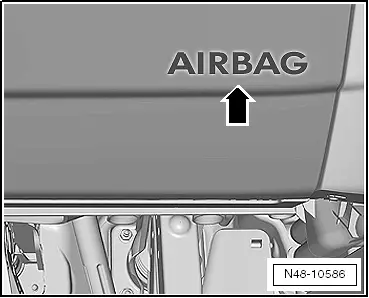
| If „AIRBAG“ appears on trim under steering column, this means a knee airbag is installed. |
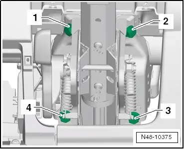
| The replacement steering column is only supplied as a complete unit. Cannot be repaired. |

WARNING | The following conditions must be met before starting work on the electrical system and removing the steering wheel: |
| Mechanic(s) must electrostatically discharge himself/themselves. This can be done by touching a suitable metal part, for example, a water pipe, a heater pipe, a metal frame or a lifting platform → Chapter. |
| Failure to comply with this precaution may lead to subsequent failure of the electronic steering column lock control unit -J764-! |
| t
| Wheels must be in straight-ahead position. |
| Failure to comply with these precautions may lead to subsequent failure of the airbag system! |
|
| –
| Turn wheels to straight ahead position. |
| –
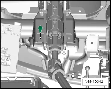
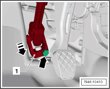
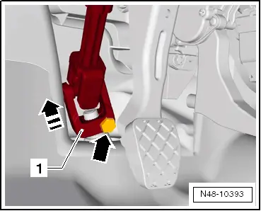
| Pull down lever on side of steering column. |
| –
| Swing steering column down as far as possible and pull out. |
| –
| Press lever on side of steering column back up. |
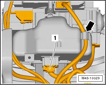
| Vehicles with ignition/starter switch |
|
|
|

 Note
Note
 Caution