seat Workshop Repair Guides

SEAT Workshop Service and Repair Manuals

Servotronic solenoid valveN119 : Removing and installing > < Power steering box: Assembly overview:
Remove and fit the power steering box .
Consult the equivalence table for tools and equipment according to applicability between Seat / VW / Audi / Skoda → Chapter.
Special tools and workshop equipment required
   
t  Hose clamps -3094-, see equivalent → Anchor
  W00-0079
t  Steering centring bolt -VAS 6224-
t  Special tools -T40067-
t  Torque wrench -V.A.G 1331-, see equivalence → Anchor
t  Torque wrench -V.A.G 1332-, see equivalence → Anchor
t  Open-end ring spanner insert (19 mm and 22 mm; commercially available type)
Removal:
–  Remove cowl → Body - outer assembly work; Rep. gr. 50
–  Disconnect battery and remove if required → Electrical system; Rep. gr. 27
  WARNING
Keep the steering wheel straight and do not rotate it during repairs, otherwise the coil connector of the airbags could be damaged.
–  Detach the ignition key if steering wheel is in centre position.
–  Move steering wheel slightly so that steering lock engages.
–  Remove stowage shelf on driver side →  Body - interior body assembly work ; Rep. gr. 68
  W00-1379
–  Unscrew mounting bolts -Arrow- on steering column on steering gear.
–  Secure steering column to prevent the two sections from pulling apart → Anchor, Securing steering column prior to removal.
  Note
t  Always renew bulkhead seal → Item if damaged.
t  Ensure that the bulkhead seal is placed correctly.
  A48-0368
–  Disconnect the supply and return fuel lines with the -3094- hose clamp.
–  Remove front wheels.
  A48-0054
–  Loosen bolted connection on spring strut/trapezoidal link (only on left side of vehicle)
–  Seen in the driving direction, mount the coil spring, bumper and mounting bracket as a unit -1- in front of the A-arm -2-.
  A48-0374
–  Loosen nut -1-, take out hexagon bolt and pull out both upper links -2- upwards (only on left side of vehicle).
Do not attempt to enlarge slots in wheel bearing housing using a chisel or similar.
–  Remove hexagon bolt -3- and detach bolt connection -4-.
–  Pull the steering link for detaching the steering rod or press down.
  Note
  A40-0473
t  Do not use any chisel or similar tool between the steering rod -1- and the washer -2- of the joint of the track rod to adjust the track rod. That would damage the washer.
t  To separate the track rod from the steering rod, use only a wooden head or rubber hammer to apply pressure or to impact the stud end of the track rod.
  A40-0475
–  Fasten wheel bearing housing -1- with tensioning strap -2- to coil spring, shock absorber and mount -3- on left side of wheel bearing housing.
  A48-0448
–  Unscrew sheet metal nuts -arrows-.
–  Lever out clips.
–  Unhook line.
–  Remove plastic cover
  A48-0056
–  Loosen bolt -1- approx. one turn.
–  Unscrew bolts -2- and -3-.
–  Pivot steering box forwards in direction of travel on driver's side.
–  Place catch vessel below steering gear to catch hydraulic oil running out.
  A48-0373
–  Unscrew the banjo bolts from steering gear for pressure hose (SW 22 mm).
On certain engine/ gearbox versions, the banjo bolt can be unscrewed only from the wheel house.
For this purpose use 22 mm box spanner attachment.
  N48-0253
–  Unscrew the banjo bolts for pressure hose (SW 19 mm) -arrow- from steering gear.
On certain engine/ gearbox versions, the banjo bolt can be unscrewed only from the wheel house.
For this purpose use 19 mm box spanner attachment.
  N48-0254
–  Unscrew bolt -1-.
–  Remove servo steering box through the wheel housing at left (two mechanics required).
  Note
Ensure that bulkhead seal is not damaged by steering box pinion.
Installation
Installation is carried out in the reverse sequence; note the following:
  A48-0373
Before installing, centralise steering box using steering centring bolt - VAS 6224-.
–  To do this, remove hexagon socket head bolt -1- on steering box.
–  Move the gear rack until centre marking (indentation) on rack -arrow- aligns with threaded hole -2-.
–  Screw in steering centring bolt -VAS 6224- hand-tight.
–  Apply lubricant G 052 745 A3 to steering box where bulkhead seal is attached.
–  Place the steering gear in the water tank area (the help of a second mechanic is required).
Make sure threads and contact surfaces of bolts are free from oil and grease.
  A48-0529
–  Insert bolt -1- but do not tighten.
–  Pivot steering box forwards in direction of travel on driver's side.
  A48-0373
–  Unscrew return hose and tighten hollow screw -2- (SW 22) to specified tightening torque → Item
–  Screw on return line and tighten hollow screw with check valve -1- (SW 19) to specified tightening torque → Item
  Note
t  Always use new seals for banjo bolts.
t  The pressure hose and return hose must not bear /rub on any other unit.
The banjo bolts can be bolted simply from the wheel housing in case of certain types of engine and gear boxes.
For this purpose use 22 mm box spanner attachment
–  Install the bulkhead seal again and control its correct position.
The projection of the bulkhead seal should match with the marking on the car body.
  Note
t  A damaged bulkhead seal should be replaced.
t  Ensure the correct position!
  A48-0377
–  Insert bolt -2- but do not tighten.
–  Screw in bolt -3- and tighten to specified tightening torque. → Item
–  Now tighten bolts -1- and -2- to specified tightening torque → Item
–  Release steering lock.
–  Keep the steering wheel straight and then fit the universal joint on the steering pinion.
  A48-0373
–  Tighten bolt -2- to specified tightening torque. → Item
–  Remove assembly aid from steering column.
–  Remove cowl → Body - outer assembly work; Rep. gr.50
–  Fit plastic cover on the mudguard.
–  Attach electrical wire.
  A48-0368
–  Fit joint pins of both upper links in wheel bearing housing and press down as far as possible by clamping with special tool -T40067 -.
  A40-10016
–  Insert new bolt -2- and self-locking nut and tighten to specified tightening torque → Item
–  Insert the fork head of the coil spring, shock absorber and mounting bracket as a unit in the track control link and tighten the bolt connection -1- tightly by hand.
  Note
Bonded rubber bushes can only be turned to a limited extent. The mountings of the suspension links must therefore only be tightened when the suspension is in the unladen position → Chapter.
  A40-0049
–  Insert the track rod up to the stop in the steering rod.
  Note
  A40-0473
Mount the track rod (only by hand) in the track control link -1-, the washer -2- of the track rod head must not bear the load.
  A40-0475
–  Install bolted connection -4- and tighten nut to specified tightening torque. → Item
–  Screw in bolt -3- and tighten to specified tightening torque. → Item
  A40-0473
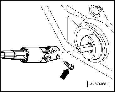
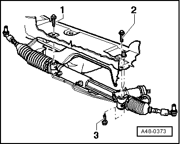
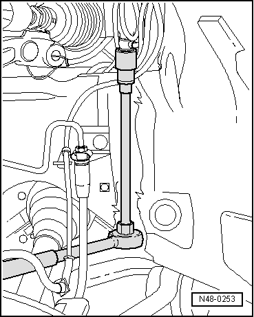
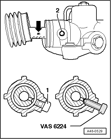
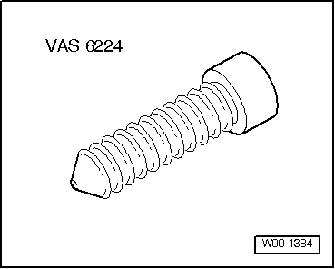
–  Now unscrew steering centring bolt -VAS 6224- from steering box.
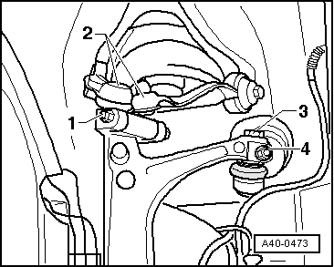
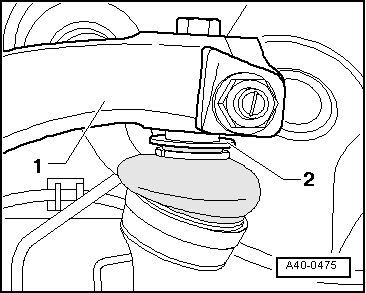
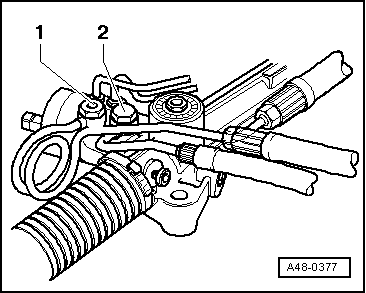
1  - Hexagon socket head bolt
2  - Threaded hole in steering box
–  Seal off steering box with hexagon socket head bolt -1- → Fig..
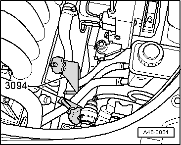
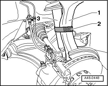
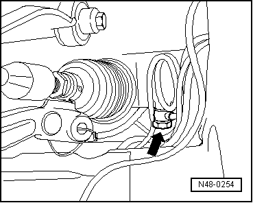
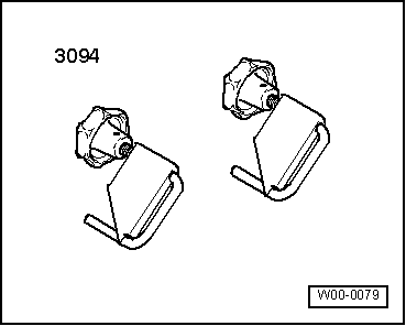
–  After the complete assembly of the steering box, remove the hose clamps -3094- again.
–  Disconnect battery and install, if required → Electrical system; Rep. gr. 27
–  Mount the wheels and the tighten the wheel bolts → Running gear, axles, steering; Rep. gr.44
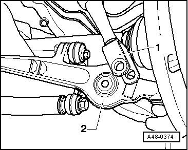
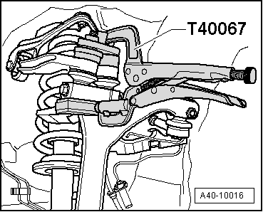
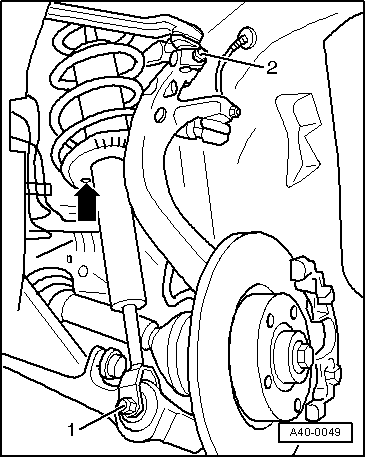
–  Tighten the bolt connection of the coil spring, bumper and mounting bracket /track control link as a unit in the specified tightening torque → Item
–  Check hydraulic fluid level → Chapter.
–  Vent the steering system. → Chapter
–  Check steering system for leaks → Chapter.
–  Wheel alignment → Chapter
Setting of the running gear must be done with an alignment stand recommended by SEAT.
  A48-0529

Servotronic solenoid valveN119 : Removing and installing > < Power steering box: Assembly overview: