seat Workshop Repair Guides

SEAT Workshop Service and Repair Manuals

Rear suspension, drive shaft > < Removing and installing drive shafts on vehicles with manual gearbox 02N
Removing and installing drive shafts on vehicles with automatic gearbox 09B
Special tools and workshop equipment required
   
t  Torque wrench -V.A.G 1332-
  W00-0428
t  Remover -T10103-
Removing
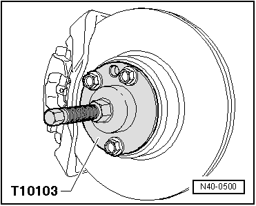
The wheel bearings must not be loaded while a hexagon bolt is loose.
If wheel bearings are loaded with weight of vehicle, bearing will be damaged. This reduces the service life of the wheel bearing.
If a vehicle has to be moved after removing the drive shaft, first install outer joint and tighten to 50 Nm otherwise the wheel bearing will be damaged.
Left drive shaft
–  Lift vehicle until the load on the front axle is relieved.
–  Remove hexagon bolt for drive shaft.
–  Remove wheel and raise vehicle.
–  Remove noise insulation tray.
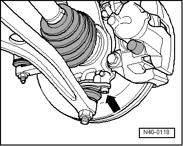
–  Disconnect drive shaft from gearbox drive flange.
  W00-1159
–  Separate bolted connection for wheel bearing housing/lower swivel joint -arrow-.
Vehicles from 04.00
  N40-0118
–  Press out drive shaft.
  Note
When pressing drive shaft out ensure sufficient clearance is available.
Continuation for all vehicles
–  Swing suspension strut outwards and support.
–  Remove drive shaft.
Right drive shaft
–  Lift vehicle until the load on the front axle is relieved.
–  Remove hexagon bolt for drive shaft.
–  Remove wheel and raise vehicle.
–  Remove noise insulation tray.
  N40-0500
–  Separate bolted connection for wheel bearing housing/lower swivel joint -arrow-.
Vehicles from 04.00
  N40-0118
–  Press out drive shaft.
  Note
When pressing drive shaft out ensure sufficient clearance is available.
Continuation for all vehicles
–  Swing suspension strut outwards and support.
–  Position oil drip pan or similar item beneath.
–  Pull drive shaft forcefully out of flange shaft. The inner joint can be pressed out of flange shaft with an assembly lever, if necessary.
Installing
Remove any paint residue and/or corrosion on thread/splines of the outer joint.
Vehicles from 04.00
–  Before inserting drive shaft, apply oil to the following:
t  The splines of the outer joint
t  The thread of the outer joint
t  The splines in the hub
t  The contact surface and thread of the 12-point nut
Continuation for all vehicles
Left drive shaft
–  Insert drive shaft.
–  Position inner joint on drive flange.
–  Tighten bolts.
–  Guide outer joint into wheel hub splines as far as possible.
–  Fit hexagon bolt for drive shaft and tighten to approx. 50 Nm.
–  Bolt swivel joint to wheel bearing housing.
–  Lower vehicle.
–  Depress brake pedal (second mechanic required).
–  Tighten drive shaft hexagon bolt.
Right drive shaft
–  Renew circlip on the splines of the inner joint.
–  Coat splines of the right inner joint with lubricating grease -G 000 603-.
–  Drive right inner joint onto drive shaft to stop.
–  Push the inner joint in until it stops by tapping lightly with a plastic hammer.
–  Guide outer joint into wheel hub splines as far as possible.
–  Fit hexagon bolt for drive shaft and tighten to approx. 50 Nm.
–  Bolt swivel joint to wheel bearing housing.
–  Lower vehicle.
–  Depress brake pedal (second mechanic required).
–  Tighten drive shaft hexagon bolt.
  N40-0500
Specified torques
BoltSpecified torque
Swivel joint to wheel bearing housing55 Nm
Drive shaft to hub
t  Use new bolt
150 Nm + 90° further
Drive shaft to flange shaft/gearbox
t  Use new bolts
70 Nm
t  Initially tighten diagonally to 10 Nm
Wheel bolts to wheel hub → Chapter


Rear suspension, drive shaft > < Removing and installing drive shafts on vehicles with manual gearbox 02N