seat Workshop Repair Guides

SEAT Workshop Service and Repair Manuals

Fuse holder and beam in engine compartment, with battery luggage compartment: remove and install > < Electronics box on left side of engine compartment (engine compartment E-box)
Removing and installing E-box on left side of engine compartment (engine compartment E-box)
  Caution
To disconnect and reconnect the battery, the procedure described in the workshop manual should be strictly adhered to → Chapter.
Removing:
–  Disconnect battery.
   
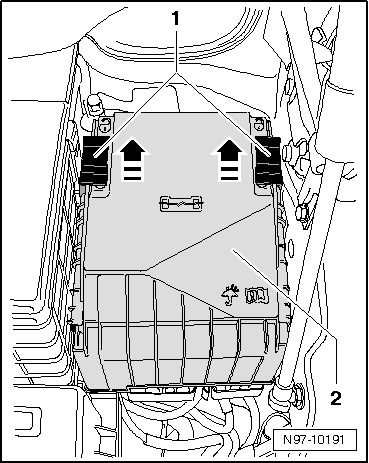
–  Push safety clip -1- in -direction of arrow- and remove cover from E-box -2- upwards.
  Caution
t  Electrical components that are protected by the multiple fuse may fail, e.g. the electromechanical power steering!
t  The multiple fuse will be damaged when the hexagon nuts of wire connections are loosened!
t  Renew the multiple fuse after loosening any connection!
  N97-10190
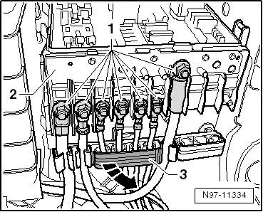
–  Unscrew hexagon nuts -1-.
–  Open cable guide covers of E-box -3- in -direction of arrow-.
–  Remove wires from connecting bolts.
–  Unclip wiring from wiring guides.
–  Renew multiple fuse -2- after loosening hexagon nuts -1-.
  N97-11334
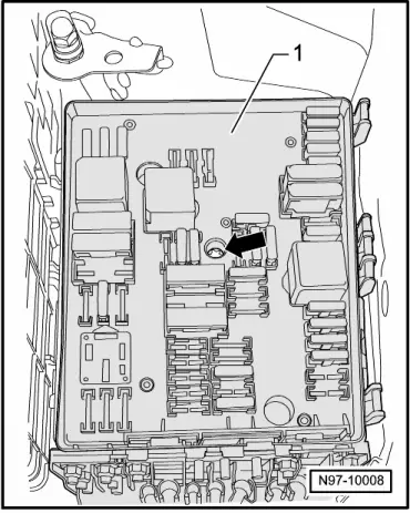
–  Unscrew central bolt -arrow- of E-box -1-.
  Note
When the central bolt -arrow- is removed, the E-box -1- is pushed upwards off the E-box holder.
–  Pull E-box -1- upwards off bracket of E-box.
  Note
  N97-10008
To remove the flat contact housing -1-, the air filter housing (on vehicles with diesel engine only), the battery and the battery console must first be removed.
–  If necessary, remove air filter housing.
–  Remove battery
  N97-10007
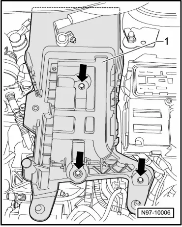
–  Undo and remove bolts -arrows- of battery console -1-..
–  Remove battery console -1- from vehicle.
  N97-10006
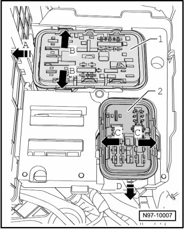
–  Push apart tabs on bracket of E-box -arrows B- and slide out flat contact housing -1- sideways -arrow A- from bracket of E-box.
–  Push apart tabs on bracket of E-box -arrows C- and slide out flat contact housing -2- forwards -arrow D- from bracket of E-box.
  N97-10007
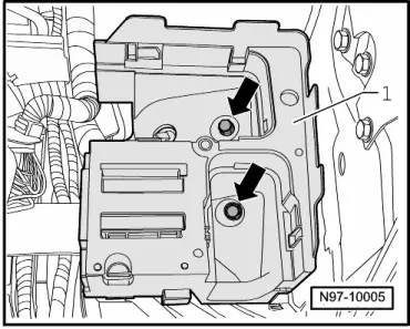
–  Remove securing nuts -arrows- from bracket of E-box -1-.
  Note
The installation of an additional relay carrier depends entirely on the vehicle equipment.
–  Pull bracket of E-box -1- upwards off studs, taking connected wiring length into consideration.
  N97-10005
–  Unclip additional relay carrier -1- sideways out of bracket of E-box -2-.
–  Remove E-box -2-retainer from vehicle.
Installing:
Installation is carried out in the reverse sequence; note the following:
–  Tighten securing bolts or securing nuts to specified torque settings.
  Caution
t  Electrical components that are protected by the multiple fuse may fail, e.g. the electromechanical power steering!
t  The multiple fuse will be damaged when the hexagon nuts of wire connections are loosened!
t  Renew the multiple fuse after loosening any connection!
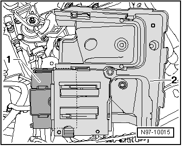
  N97-10015
Tightening torques: E-Box on the left side of the engine compartment
  N97-11334
Threaded connections Tightening torques
Securing nuts -1-M5 (8 mm)4 Nm
Securing nuts -1-M6 (10 mm)6 Nm
Electronics box central bolt 9 Nm

   
–  Slide cover -2- on E-box and push safety clip -1- in -direction of arrow- until cover -2- engages.
  Note
Then check whether the cover -2- of the E-box is engaged correctly.
  N97-10191

Fuse holder and beam in engine compartment, with battery luggage compartment: remove and install > < Electronics box on left side of engine compartment (engine compartment E-box)