
Leon Mk2
| ABS TRW (ABS/EDL/TCS/ESP) |
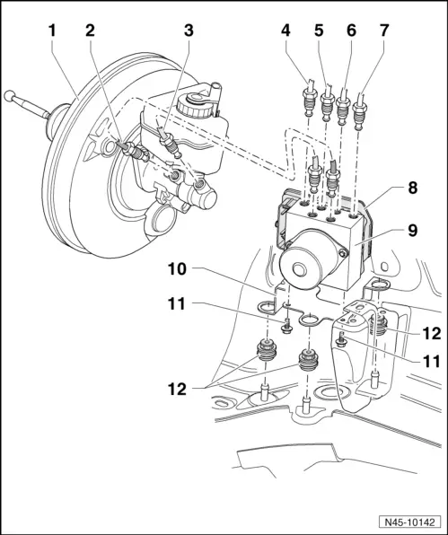
| 1 - | Brake servo unit |
| q | removing and fitting → Chapter |
| 2 - | Brake line, 14 Nm |
| q | Master brake cylinder / pressure-rod piston circuit to hydraulic unit |
| q | Marking: Ø 6.5 mm and threaded pipe with long thread M 12 x 1 |
| q | Marked on hydraulic unit with „HZ1“ |
| 3 - | Brake line, 14 Nm |
| q | From secondary piston circuit of brake master cylinder to hydraulic unit. |
| q | Marking: Ø 6.5 mm and threaded pipe with long thread M 12 x 1 |
| q | Marked on hydraulic unit with „HZ2“ |
| 4 - | Brake line, 14 Nm |
| q | To front right brake caliper |
| q | Marking: Ø 5.25 mm and threaded pipe bolt M 10 x 1 |
| q | Marked on hydraulic unit with „VR“ |
| 5 - | Brake line, 14 Nm |
| q | To rear left brake caliper |
| q | Marking: Ø 5.25 mm and short threaded pipe bolt M 12 x 1. |
| q | Marked on hydraulic unit with „HL“ |
| 6 - | Brake line, 14 Nm |
| q | To rear right brake caliper |
| q | Marking: Ø 5.25 mm and threaded pipe bolt M 10 x 1 |
| q | Marked on hydraulic unit with „HR“ |
| 7 - | Brake line, 14 Nm |
| q | To front left brake caliper |
| q | Marking: Ø 5.25 mm and short threaded pipe bolt M 12 x 1. |
| q | Marked on hydraulic unit with „VL“ |
| 8 - | ABS control unit -J104- |
| The control unit and hydraulic unit cannot be separated. |
| q | removing and fitting → Chapter |
| 9 - | ABS hydraulic unit -N55- |
| The control unit and hydraulic unit cannot be separated. |
| q | removing and fitting → Chapter |
| 10 - | Spring retainer |
| 11 - | Torx socket head bolt, 8 Nm |
| 12 - | Rubber damper |