
Leon Mk2
| Brake servo / Master brake cylinder: general assembly diagram |
 Note!
Note!| The master brake cylinder and the servo brake can be replaced independently. |
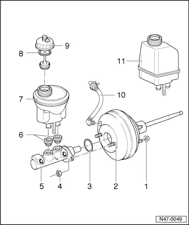
| 1 - | Nut, self-locking |
| q | 25 Nm |
| 2 - | Brake servo |
| q | In petrol engines, the necessary vacuum is taken from the intake manifold. |
| q | In diesel engines the vacuum is obtained by a fitted vacuum pump. |
| q | Functional check |
| – | With engine off, strongly depress the brake pedal several times (this reduces the existing vacuum in the aparatus). |
| – | Next, keep the brake pedal depressed halfway and start engine. If the servo brake is working correctly the brake pedal will give way noteably (the servo brake effect is beginning). |
| q | Separating from brake pedal → Chapter |
| q | Non return valve (in the vacuum hose) → Anchor |
| Checking functioning: |
| → Anchor |
| 3 - | Sealing ringing |
| q | Renew |
| 4 - | Nut, self-locking |
| q | 20 Nm |
| 5 - | Master brake cylinder |
| q | Reworking is not permitted. If faulty, completely replace. |
| 6 - | Gasket plugs |
| q | Impregnate with brake fluid and introduce into the expansion tank |
| 7 - | Brake fluid deposit, vehicles with left-hand drive |
| 8 - | Gasket |
| 9 - | Sealing cap with brake fluid level switch |
| 10 - | Vacuum hose |
| q | With non-return valve |
| Checking functioning: |
| → Anchor |
| 11 - | Brake fluid deposit, vehicles with right-hand drive |