skoda Workshop Repair Guides

Skoda Workshop Service and Repair Manuals

Hydraulic control unit (ABS systems BOSCH 5.7), Brake servo unit/Master brake cylinder > < Removing and installing steering angle senderG85 - vehicles with ABS/EDL/TCS/ESP BOSCH 5.7 or ABS/TCS/ESP BOSCH 8.0
Removing and installing lateral acceleration senderG200 and yaw rate senderG202 or ESP sensor unitG419 - vehicles with ABS/EDL/TCS/ESP BOSCH 5.7 or ABS/TCS/ESP BOSCH 8.0
Removing and installing lateral acceleration sender -G200- and yaw rate sender -G202- or ESP sensor unit -G419- - vehicles with ABS/EDL/TCS/ESP BOSCH 5.7 or ABS/TCS/ESP BOSCH 8.0
  Note
t  lateral acceleration sender -G200- and yaw rate sender -G202- are combined in one housing for the ABS/EDS/ASR/ESP BOSCH 5.7.
t  Only the ESP sensor unit -G419- for the ABS/ASR/ESP BOSCH 8.0 exists. The lateral acceleration sender -G200- and the yaw rate sender -G202 - are integrated in it.
t  The removed unit is sensitive to strong vibrations.
t  If the unit was exposed to strong vibrations or blows, its proper operation cannot be guaranteed.
Special tools and workshop equipment required
t  Vehicle system tester -V.A.G 1552- or vehicle diagnosis, measurement and information system -VAS 5051-
t  Diagnostic cable -V.A.G 1551/3-, -V.A.G 1551/3A-, -V.A.G 1551/3B-, - V.A.G 1551/3C-, -VAS 5051/5A- or -VAS 5051/6A-
Removing:
  WARNING
t  Disconnect earth strap from the battery before commencing work on the electrical system.
t  If the battery earth strap is disconnected and connected, carry out certain additional operations → Electrical System → Rep. gr.27.
–  Disconnect battery → Electrical System → Rep. gr.27.
–  Remove left front seat → Body Work → Rep. gr.72.
–  Remove bottom trim panel of pillar B → Body Work → Rep. gr.70.
–  Partially remove bottom trim panel of pillar A → Body Work → Rep. gr.70.
  Note
t  
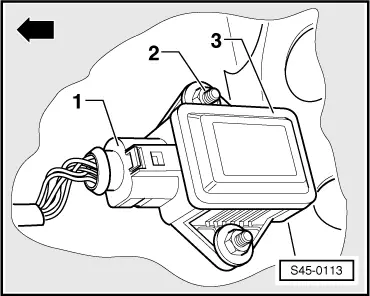
The unit is located under the base of the left front seat before the cross member.
t  -Arrow- in Fig. S45-0113 points in the travel direction.
   
–  Unplug plug -1- from the unit -3-.
–  Unscrew nuts -2- and remove unit -3-.
Installing:
Installation is performed in the reverse order, pay attention to the following points:
–  Connect battery → Electrical System → Rep. gr.27.
–  Perform automatic test sequence → Chapter either using the vehicle system tester -V.A.G 1552- or the vehicle system test → Chapter using the vehicle diagnosis, measurement and information system -VAS 5051-
If a fault is stored in the fault memory:
vehicles with ABS/EDL/TCS/ESP BOSCH 5.7
–  Remove fault → Chapter
–  Erasing fault memory → Chapter
Vehicles with ABS//TCS/ESP BOSCH 8.0
–  Remove fault → Chapter
–  Erasing fault memory → Chapter
  S45-0113
Tightening torques:
Sender -G200/G202- on body (ABS/EDL/TCS/ESP BOSCH 5.7)6 Nm
ESP sensor unit -G419- on body (ABS/TCS/ESP BOSCH 8.0)6 Nm


Hydraulic control unit (ABS systems BOSCH 5.7), Brake servo unit/Master brake cylinder > < Removing and installing steering angle senderG85 - vehicles with ABS/EDL/TCS/ESP BOSCH 5.7 or ABS/TCS/ESP BOSCH 8.0