skoda Workshop Repair Guides

Skoda Workshop Service and Repair Manuals

Securing the engine to the assembly stand > < Removing and installing engine
Removing engine
Removing engine
  Note
t  The engine is removed downwards together with the gearbox.
t  Jacking up points for raising the vehicle → Fabia.
t  The hose connections are secured with screw-type clips, spring-type clips or clamp-type clips. Always replace warm-type clamps with spring strap clips or screw clamps.
t  Fuel hoses at the engine must only be secured with spring-type clips. The use of clamp-type or screw-type clips is not allowed.
t  Use pliers for spring strap clips to fit the spring strap clips.
t  All cable straps that have been loosened or cut open when the engine was removed must be attached again in the same location when the engine is installed again.
t  Pay attention to the correct assignment of the plugs, if necessary mark.
t  Collect drained coolant in a clean container for proper disposal or reuse.
Work procedure
  WARNING
Observe measures when disconnecting the battery → Electrical System; Rep. Gr.27.
–  Disconnect the battery-earth strap with the ignition off.
   
–  Remove the sound dampening system → Body Work; Rep. Gr.50.
–  Remove drive shaft to the right → Chassis; Rep. Gr.40.
–  Unscrew the left drive shaft from the gearbox flange.
–  Lift the left drive shaft upwards and tie up.
–  Remove pre-exhaust pipe with catalytic converter → Chapter.
  S10-0114
–  Release screw -3-.
–  Remove charge-air pipe at bottom -1- with connecting hose -2--arrows-.
  S10-0147
–  Unbolt the pendulum support -arrows-.
–  Drain coolant → Chapter.
  S34-0337
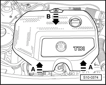
–  Lift the engine cover at the sides -arrows A- and pull out towards the front -arrow B-.
–  Remove air filter with intake hose → 1.9/96 TDI Engine, Fuel Injection; Rep. Gr.23.
–  Remove battery and battery tray → Electrical System; Rep. Gr.27.
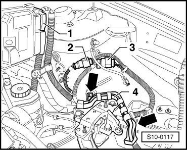
–  Unscrew the generator cables from the battery cover and remove the wiring loom from the holder.
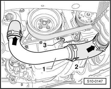
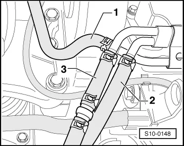
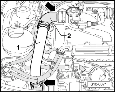
–  Remove the coolant hoses from the radiator.
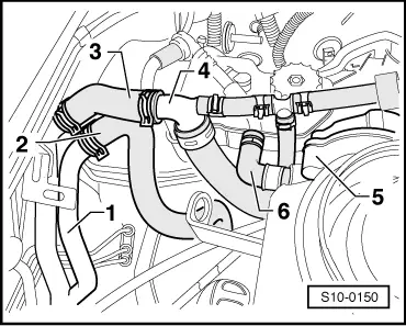
–  Disconnect the plugs of the radiator fans, unscrew fixing bolts for fan shroud and remove the fan shroud from the radiator together with the installed fans → Chapter
For vehicles with air conditioning
  WARNING
Refrigerant circuit of the air conditioning system must not be opened.
  Note
In order to avoid damage to the AC compressor as well as to the refrigerant lines and hoses, ensure that the lines and hoses are not over-tensioned, kinked or bent.
–  Remove AC compressor from compact holder → Heating, Air conditioning; Rep. Gr.87, the lines remain connected.
–  Hang the air-conditioning compressor with its attached lines on the lock carrier.
–  Remove the generator → Electrical System; Rep. Gr.27.
For all vehicles
  S10-0374
–  Disconnect the coolant hose -1- from the cylinder head.
–  Disconnect the fuel intake hose -3- and the fuel return hose -2- from the pipes.
–  Seal the lines in order to prevent any dirt from penetrating into the fuel system.
  S10-0148
–  Remove charge-air pipe at the top -1- with connecting hose -2--arrows-.
–  Pull off the coolant hose from the expansion bottle at the bottom.
–  Remove the vacuum hoses from all the connecting points at the engine or from the valve block → Chapter.
  S10-0371
–  Remove the coolant feed hose -3- from the supports -4-.
–  Remove the coolant return hose -2- from the heat exchanger connection fittings -1-.
–  Pull off vacuum hose -6- from tandem pump -5-.
  S10-0150
–  Unplug connector -1- from the engine control unit.
–  Disconnect the plug connections -2- and -3- and remove from bracket.
–  Unclip cable clip -4--arrows-.
  S10-0117
–  Remove Bowden cable support -arrows-.
–  Pull out slave cylinder line -A- from the holder on the gearbox.
  S10-0152
–  Remove the gearshift mechanism -1- and -2- from the gearbox → Gearbox; Rep. Gr.34.
–  Raise control cables and secure.
–  Disconnect plug -3- from the reversing light switch -F4-.
–  Release earth strap -4- from the frame side rail.
–  Unplug connector -5- and the cable -6- from the starter.
  S10-0153
–  Remove slave cylinder -B-, lay aside and secure with wire. Do not open line system.
  WARNING
After removing the slave cylinder or after separating the hydraulic line, do not depress the clutch pedal.
  A30-0048
–  Disconnect the plug connections -2- and -3- under the starter and remove from bracket.
–  Insert engine mount -T10012- into engine/gearbox jack (e.g. -V.A.G 1383 A-).
  S10-0151
–  Screw the engine mount -T10012- to the cylinder block using fixing nut and screw M10 x 25/8.8 and tighten to approx. 40 Nm.
–  Raise the engine and gearbox with the engine/gearbox jack (e.g. -V.A.G 1383 A-).
  Note
Use double ladder (e.g.-VAS 5085-) to release the screws for the engine/gearbox mounting.
  N10-0056
–  Unscrew the engine mount from the engine support -arrows-.
  Note
If the engine/gearbox unit drops when the screws are released raise it up again.
  S10-0149
–  Unscrew the gearbox mount from the gearbox support -arrows-.
  Note
t  Check whether all hose and line connections between engine, gearbox and body are released.
t  Carefully guide the engine and gearbox during the lowering operation. Ensure adequate clearance to neighbouring components in the engine compartment and body in order to avoid damage.
–  Carefully lower the engine with gearbox.
–  Remove the gearbox from the engine → gearbox; Rep. Gr.34.
  S10-0120

Securing the engine to the assembly stand > < Removing and installing engine