Turn crankshaft 2 turns in the direction of running of the engine until the crankshaft is positioned shortly before TDC for cylinder 1.
Note
t
The bolt of the crankshaft arrester -T10050- must engage in the sealing flange. (The crankshaft arrester should be inserted just ahead of TDC on toothed belt sprocket.)
t
If the crankshaft is positioned after the TDC of the piston for cylinder 1 and the bolt of the crankshaft arrester does not engage in the sealing flange, rotate the crankshaft back 1/4 revolution and again set the crankshaft to the TDC of the piston for cylinder 1 by turning in direction of rotation of engine.
t
It is not permitted to carry out the correction by turning in the opposite direction of rotation of the engine in order to insert the crankshaft arrester.
For vehicles ? 04.01
–
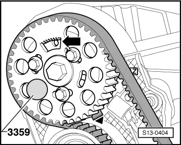
Interlock during this motion the hub in the direction of running of the engine with locking pin -3359- or -MP 1-301-.
–
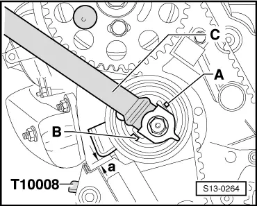
Lock the crankshaft with crankshaft arrester -T10050- and check the dimension -a- 4 ± 1 mm.
If dimension -a- is not reached:
–
Tighten the tensioning pulley.
Hold the tensioning pulley with the wrench, slacken the nut, and turn the wrench clockwise until dimension -a- is achieved.
Specified dimension -a-: 4 ± 1 mm.
If dimension -a- is reached:
–
Tighten fixing nut again to 20 Nm + torque a further 45° (1/8 turn).
For vehicles 05.01 ?
–
Interlock during this motion the hub in the direction of running of the engine with locking pin -3359- or -MP 1-301-.
–
Check whether:
t
the crankshaft can be interlocked with the crankshaft arrester -T10050-.
t
The pointer of tensioning pulley stands in the centre or max. 5 mm to the right from the gap of the base plate.
For all vehicles
If the crankshaft cannot be arrested:
–
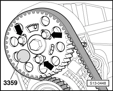
Loosen the screws -arrows- of the camshaft sprocket.
–
Rotate the crankshaft in direction of rotation of engine until the crankshaft can be arrested with the crankshaft arrester -T10050-.
Note
If the crankshaft can be turned via the TDC for cylinder 1, turn crankshaft back slightly and once again set to the TDC for cylinder 1 by turning in direction of rotation of engine.
–
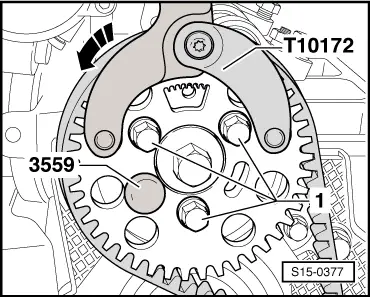
Position the counterholder -T10172- at the camshaft sprocket as shown and pretension the timing belt in the -direction of the arrow-.
–
Keep the fixing screws -1- of the camshaft sprocket under tension to 20 Nm + torque a further 45° (1/8 turn).
–
Remove locking pin -3359- or -MP 1-301- and crankshaft arrester -T10050-.
–
Rotate crankshaft on a further two revolutions in direction of rotation of the engine until the crankshaft is again positioned at TDC of piston of cylinder 1.
–
Repeat timing test.
Further installation occurs in reverse order.
Tightening torque of the engine mount and pendulum support: → Chapter.
 Note
Note