
Fabia Mk1
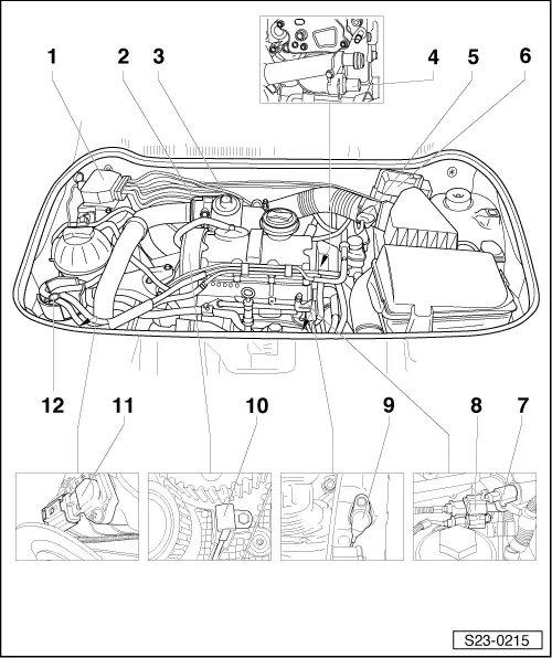
| Overview of fitting locations |
| Components A through H are not represented in the overview figure. |
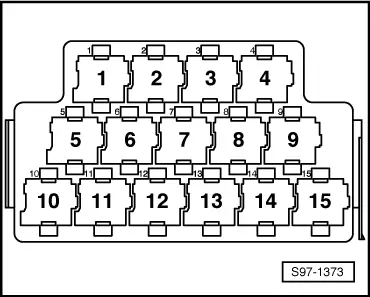
| A - | Diesel direct injection system relay -J322- |
| q | on relay carrier → Fig. |
| B - | Glow plug relay -J52- |
| q | on relay carrier → Fig. |
| C - | Low heat output relay -J359- |
| q | on relay carrier → Fig. |
| D - | High heat output relay -J360- |
| q | on relay carrier → Fig. |
| E - | Fuel pump relay -J17- |
| q | on relay carrier → Fig. |
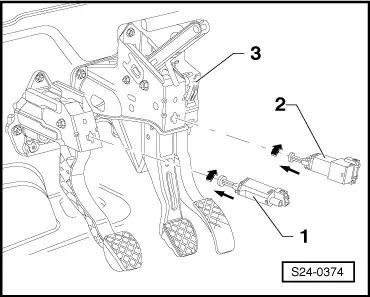
| F - | Sender for accelerator pedal position -G79- |
| q | in footwell on the accelerator pedal → Fig. |
| G - | Brake light switch -F- and Brake pedal switch -F47- |
| q | in footwell on the brake pedal → Fig. |
| H - | Clutch pedal switch -F36- |
| q | in footwell on the clutch pedal → Fig. |
| 1 - | Valve block |
| q | Component parts of the valve block are: |
| q | Valve for exhaust gas recirculation -N18-, specified resistance: 14...20 Ω |
| q | solenoid valve for charge pressure control -N75-, specified resistance: 25...45 Ω |
| q | dor engine with identification characters AMF: intake manifold flap change-over valve -N239-, specified resistance 25...45 Ω |
| 2 - | Intake manifold flap motor -V157- |
| q | for engine with identification characters BNM, BNV |
| 3 - | Mechanical exhaust gas recirculation valve |
| q | at the induction pipe with the intake manifold flap |
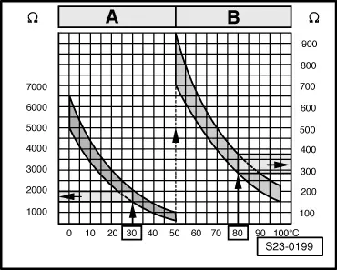
| 4 - | Sender for the coolant temperature -G62- |
| q | Specified resistance → Fig. |
| 5 - | Air mass meter -G70- |
| 6 - | Engine control unit -J248- |
| 7 - | Fuel temperature sender -G81- |
| q | Specified resistance → Fig. |
| 8 - | Plug connection |
| q | 3-pin, grey |
| q | for engine speed sender -G28- |
| q | 3-pin, black |
| q | for the camshaft position sensor -G40- |
| 9 - | Engine speed sender -G28- |
| q | specified resistance between contacts 1 and 2: 450...550 Ω |
| 10 - | Camshaft position sensor -G40- |
| 11 - | Intake manifold pressure sender -G71- with intake manifold temperature sender -G72- |
| q | Specified resistance → Fig. |
| 12 - | Fuel filter |
| q | Fuel filter shown on engine with identification characters AMF |
| q | repairing → 1.4/51; 55; 59 TDI Engine, Mechanics; Rep. Gr.20 |
|
|
|
|
|

|