
Fabia Mk1
| Repairing Valve Gear |
 Note
Note| Cylinder heads with cracks between the valve seats may continue to be used without any reduction in life provided these are slight incipient cracks which are not more than 0.5 mm wide. |

| 1 - | 20 Nm + torque a further 1/4 turn (90°) |
| q | replace |
| q | pay attention to sequence for loosening and tightening → Chapter |
| 2 - | Valve-lever shaft |
| q | do not interchange |
| 3 - | Cylinder head bolt |
| q | pay attention to sequence for loosening and tightening → Chapter |
| q | before fitting insert washers → Item in the cylinder block |
| 4 - | Washer |
| q | for cylinder head screws |
| q | insert in cylinder block before fitting the bearing cap |
| 5 - | Bucket tappets |
| q | do not interchange |
| q | with hydraulic valve clearance compensation |
| q | lay aside with contact surface facing down |
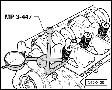
| q | before installing check axial play of the camshaft → Fig. |
| q | oil contact surfaces |
| q | before removing remove the camshaft bearing shells |
| 6 - | Collets |
| 7 - | Valve spring retainer |
| 8 - | Valve spring outside |
| q | removing and installing: |
| t | Cylinder head removed: with - MP 1-218-, - MP 1-211-, -MP 1-213- |
| t | Cylinder head fitted: → Chapter |
| 9 - | Valve spring inside |
| q | removing and installing: |
| t | Cylinder head removed: with - MP 1-218-, - MP 1-211-, -MP 1-213- |
| t | Cylinder head fitted: → Chapter |
| 10 - | Valve stem seal |
| q | replace → Chapter |
| 11 - | Valve guide |
| q | check → Chapter |
| q | if the wear limit is exceed, replace cylinder head |
| 12 - | The unit injector |
| q | removing and installing → 1.9/74 TDI Engine, Fuel Injection; Rep. Gr.23 |
| 13 - | Cylinder head |
| q | pay attention to note → Anchor |
| 14 - | PTFE gasket ring |
| q | Do not additionally lubricate or grease the sealing lips of the PTFE gasket ring |
| q | before fitting remove oil residues on the camshaft studs with a clean cloth |
| q | to fit cover slot on the camshaft cone with commercially available adhesive tape (e.g. with Sellotape) |
| q | removing and installing → Chapter |
| 15 - | Valves |
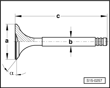
| q | Valve dimensions → Fig. |
| 16 - | Bearing shell |
| q | do not mix up used bearing shells (mark) |
| q | check correct fit of the retaining lugs in the bearing caps and cylinder head |
| 17 - | Camshaft |
| q | inspecting axial play → Fig. |
| q | removing and installing → Chapter |
| q | check radial clearance with Plastigage |
| t | Wear limit: 0.11 mm |
| q | Slack: max. 0.04 mm |
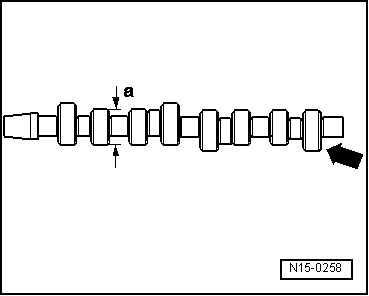
| q | Identification, timing → Fig. |
| 18 - | Bearing caps |
| q | order of installation → Chapter |
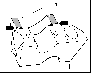
| q | seal contact surface of bearing caps 1 and 5 with sealant -AMV 174 004 01- → Fig. |
| 19 - | 8 Nm + torque a further 1/4 turn (90°) |
| q | replace |
Note
|
|
Note
|
|
| Dimension | Inlet valve | Exhaust valve | |
| Ø a | mm | 35,95 | 31,45 |
| Ø b | mm | 6,980 | 6,956 |
| c | mm | 89,95 | 89,95 |
| α | ∠° | 45 | 45 |
|
|
| Cylinder 4 -arrow- | 038 R or 858 R |