
Fabia Mk1
| Connection diagram for vacuum hoses for vehicles ► 10.01 |
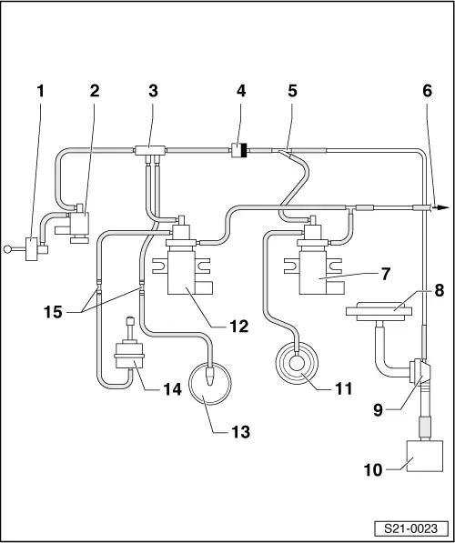
| 1 - | Vacuum unit |
| q | For intake manifold flap |
| 2 - | Changeover valve for intake manifold flap -N239- |
| 3 - | Distributor part |
| 4 - | Non-return valve |
| q | white connection points to charge pressure control solenoid valve / vacuum reservoir / switchover valve |
| 5 - | Distributor part |
| 6 - | To air filter |
| 7 - | Exhaust gas recirculation valve -N18- |
| 8 - | Brake servo unit |
| 9 - | Distributor part |
| q | With non-return valve for brake servo unit |
| 10 - | Tandem pump |
| 11 - | Mechanical exhaust gas recirculation valve |
| 12 - | Solenoid valve for charge pressure control -N75- |
| q | Checking charge pressure control → Chapter |
| 13 - | Vacuum reservoir |
| 14 - | Vacuum unit |
| q | For charge pressure control |
| q | Components of the exhaust gas turbocharger cannot be replaced individually |
| 15 - | Connecting tube |