
Fabia Mk1
 Note
Note
|
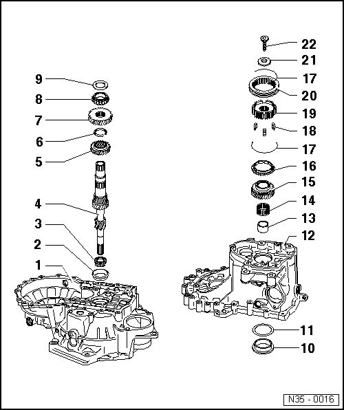
| 1 - | Clutch housing |
| 2 - | Outer ring/tapered-roller bearing |
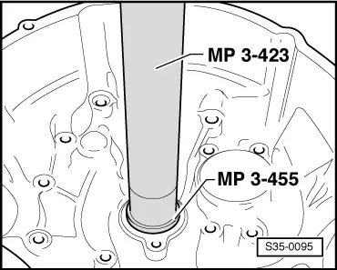
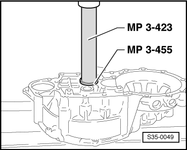
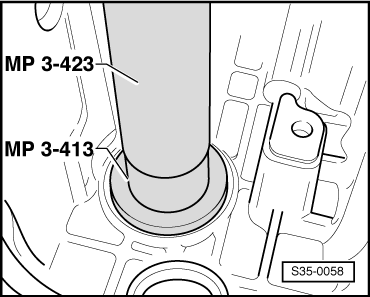
| q | pressing out → Fig. |
| q | installing → Fig. |
| 3 - | Inner ring/tapered-roller bearing |
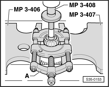
| q | pressing off → Fig. |
| q | installing → Fig. |
| 4 - | Drive shaft |
| q | adjust → Chapter |
| 5 - | 3rd gear pinion |
| q | Collar points to the 4th gear |
| q | pressing off → Fig. |
| q | pressing on → Fig. |
| 6 - | Circlip |
| q | always replace → Electronic Catalogue of Original Parts |
| 7 - | 4th gear pinion |
| q | pressing off with inner ring/tapered-roller bearing and bushing → Fig. |
| q | pressing on → Fig. |
| q | Collar points to the 3rd gear |
| 8 - | Inner ring/tapered-roller bearing |
| q | press off with 4th gearwheel and bushing → Fig. |
| q | pressing on → Fig. |
| 9 - | Thrust washer |
| 10 - | Outer ring/tapered-roller bearing |
| q | pressing out → Fig. |
| q | installing → Fig. |
| 11 - | Adjusting washer |
| q | Determine thickness → Chapter |
| 12 - | Gearbox housing |
| 13 - | Bushing |
| q | for needle bearing |
| q | press off with 4th gearwheel and inner ring/tapered-roller bearing → Fig. |
| q | pressing on → Fig. |
| q | insert thrust washer Pos. 9 before assembly |
| 14 - | Needle bearing |
| 15 - | 5th gear sliding gear |
| q | removing and installing → Chapter |
| 16 - | 5th gear synchronizer ring |
| q | with integrated arresters → Chapter |
| q | check for wear → Chapter |
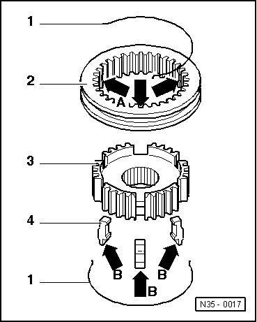
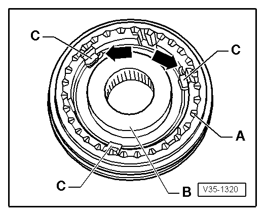
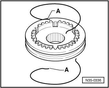
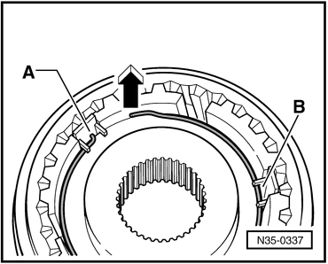
| 17 - | Spring |
| q | Fitting position → Fig. |
| q | on gearboxes as of manufacturing date 10.04 the spring was changed → Fig. |
| q | Fitting position → Fig. |
| 18 - | Arresters (3 pieces) |
| q | Fitting position → Fig. |
| q | on gearboxes as of manufacturing date 03.01 are installed the arresters, which are hollow inside |
| 19 - | 5th gear synchronizer body |
| q | removing and installing → Chapter |
| 20 - | 5th gear sliding sleeve |
| q | removing and installing → Chapter |
| 21 - | Disc spring |
| q | Fitting position → Chapter |
| 22 - | 80 Nm |
| q | holds disc spring in position with sleeve socket on screw head → Chapter |
| q | always replace → Electronic Catalogue of Original Parts |
|
|
|
|
|
|
|
|
|
|
|
|
|
|
|
|
|
|
|
|
|
|
|
|
|
|
|
|
|
|