skoda Workshop Repair Guides

Skoda Workshop Service and Repair Manuals

Installing the gearbox > < Removing and installing the gearbox
Removing the gearbox
Special tools and workshop equipment required
t  Gearbox mount -3282-
t  Adjusting plate -3282/31-
t  Engine and gearbox jack (e.g. -V.A.G 1383 A -)
t  Gearbox attachment device -MP3-478 (3336) -
t  Supporting device -MP9-200 (10-222A)-
t  Grease for plug serration of clutch disc -G 000 100-
–  Before disconnecting the battery determine the code of radio sets fitted with anti-theft coding.
–  Disconnect the battery-earth strap with the ignition off.
–  Remove engine cover → engine → Rep. Gr.10.
–  Remove battery and battery tray → Electrical System → Rep. Gr.27.
–  Remove air filter → Engine → Rep. Gr.23 or → Engine → Rep. Gr.24.
   
–  Pull forward the locking mechanism at shift cable and at selector cable as far as the stop -arrow 1-, then lock by turning to the left -arrow 2-.
Metal relay lever
–  Detach circlip -arrow 3- from the relay lever -A- and remove relay lever.
  N34-1389
Plastic relay lever
–  Carefully press down the catch -arrow 1- of the relay lever up to the stop.
–  Afterwards carefully pull relay lever out of its bearing point in the cover. To do so move relay lever back and forward (direction of operation).
Continued for all vehicles
  N34-10885
–  Remove the gearshift lever -B-, for this step unscrew nut -arrow 4-.
  N34-1389
–  Remove Bowden cable support -arrows-.
–  Tie up shift cable and selector cable.
–  Draw out the tube and hose line -A- from bracket on the gearbox.
–  Remove slave cylinder -B-, lay to one side and secure with wire. Do not open line system.
  Note
Do not depress the clutch pedal.
Vehicles with petrol engines:
  S34-0332
–  If fitted, unplug connector -arrow- from speedometer sender -G22-.
Vehicles with diesel engines:
  S34-0334
–  If fitted, unplug connector -arrow- from speedometer sender -G22-.
Continued for all vehicles:
–  Remove engine/gearbox connecting screw at the top.
–  Remove fixing screw for starter at the top.
–  Remove front left wheel and raise vehicle.
–  Remove the sound dampening system of engine/gearbox → Body Work → Rep. Gr.50.
  N34-1183
–  Release double clamp -1- and separate the exhaust system.
–  If fitted, unclip the lambda probe line from clip -2-.
  S34-0336
–  Remove the earth strap from the engine/gearbox connecting screw at the bottom front -1-.
–  Disconnect plug -2- from the reversing light switch -F4-.
–  Unscrew bracket -3- from the gearbox -arrow- and lay aside together with the lines.
–  Remove the front left wheelhouse liner → Body Work → Rep. Gr.66.
–  Remove the starter → Electrical System → Rep. Gr.27.
  S34-0347
–  Unbolt the pendulum support -arrows-.
  S34-0337
–  Remove protective cap for drive shaft (if present) from the engine -arrows-.
–  Disconnect the drive shafts from the flange shafts, turn steering wheel to the left.
  S39-0282
–  Check if a cover plate -A- is fitted above the flange shaft.
–  If present, remove cover plate -A--arrows-.
  V34-3005
–  Mark installation position of bolts -1- for left steering joint; otherwise the steering geometry must be checked.
–  Release screws -1-.
–  Unbolt anti-toll bar-coupling rod -2--arrow-.
–  Swivel out the wheel-bearing housing while guiding the drive shaft into the wheelhouse and secure to the suspension strut with e.g. wire.
–  Tie up the right drive shaft as far as possible. Avoid damaging the paintwork on the drive shaft during this operation.
–  Unscrew the engine/gearbox connecting screw above the right flange shaft.
  S39-0142
–  Install supporting device -MP 9-200-.
  Note
When installing the lifting hooks of the supporting device, pay attention to hose and cable connections in the area of the lifting eyes of the engine to avoid damaging them.
–  Take up the weight of the engine/gearbox unit at the spindles.
  S34-0335
–  Unscrew the fixing screws -arrows- from the gearbox mount.
  S34-0338
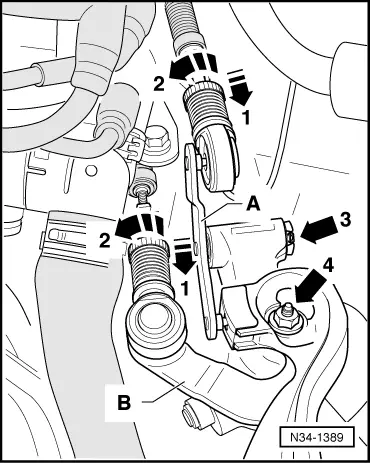
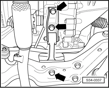
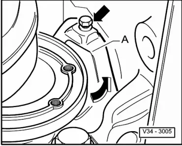
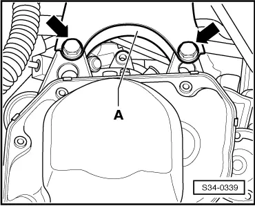
–  Detach gearbox mounting bracket -A- from the gearbox.
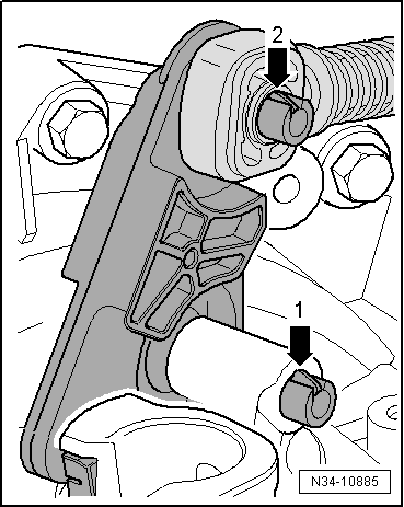
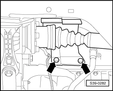
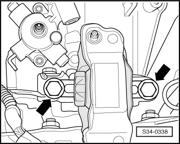
Remove the fixing screws -arrows- for the gearbox mounting bracket as follows:
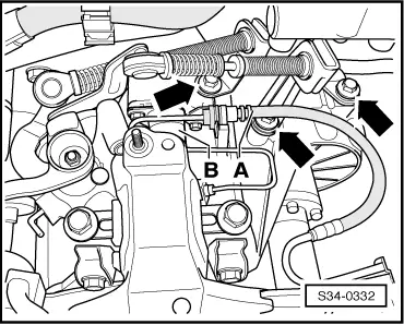
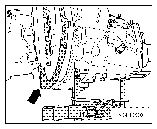
–  Lower engine/gearbox unit sufficiently at the two spindles until the fixing screws attaching the gearbox mounting bracket -A- are accessible from the left wheelhouse.
  Note
When lowering the engine/gearbox unit, make sure the gearbox does not touch the assembly carrier.
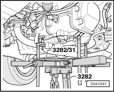
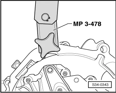
–  Insert engine mount -3282- into engine and gearbox jack, (e.g.-V.A.G 1383 A -).
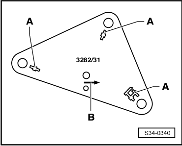
Complete engine/gearbox jack with gearbox mount -3282-, adjusting plate -3282/31- for gearbox “02T” and support elements as follows:
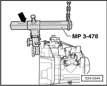
–  Position adjusting plate -3282/31- on gearbox mount -3282- (adjusting plate fits in only one position).
–  Align arms of the gearbox mount to match the holes in the adjusting plate.
  S34-0339
–  Screw in the mounting elements -A- as shown on adjusting plate.
  S34-0340
–  Position engine/gearbox jack below vehicle, ⇒ Fig. S34-0340 symbol arrow -B- on adjusting plate points in the direction of travel/vehicle.
–  Align adjusting plate parallel to the gearbox and lock securing mounts at gearbox.
–  Remove the bottom fixing screws for the engine/gearbox.
–  Press gearbox off the engine and swivel towards the assembly carrier.
For vehicles fitted with a 1.4 litre/51 kW engine:
  S34-0341
–  When lowering the gearbox, if necessary remove the inserted intermediate plate -arrow-.
Continued for all vehicles:
–  Ask a second mechanic to push the engine forwards.
–  Carefully lower the gearbox.
–  Change the gearbox position at the spindles of the gearbox mount -3282- when lowering.
  N34-10588
–  Screw down gearbox suspension device -MP3-478- onto clutch housing.
  S34-0343
–  Adjust supporting arm at slide with locking pin.
Number of visible holes = 5.
–  Raise gearbox with workshop crane and gearbox suspension device -MP 3-478-.
–  Place down gearbox, e.g. in a transport container.
  S34-0344

Installing the gearbox > < Removing and installing the gearbox