skoda Workshop Repair Guides

Skoda Workshop Service and Repair Manuals

Setting output shaft gears 1 through 4 > < Disassembling and assembling output shaft gears 1 through 4
Synchronization for 1st through 3rd gear is modified on certain gearboxes as of gearbox manufacturing date 02 10 6
These modification measures affect the following components:
t  1st through 3rd gear sliding gears
t  Synchronizer rings for 1st through 3rd gear → Fig.
t  Sliding sleeve with 1st and 2nd gear synchronizer body
t  Sliding sleeve with 3rd and 4th gear synchronizer body
  Note
t  Assign components via the → Electronic catalogue of original parts.
t  If components are not replaced, make sure that they are assigned again to the original gear.
t  Do not mix up synchronizer rings for 3rd gear with synchronizer rings for 1st and 2nd gear (have different Ø).
t  Check synchronizer rings for wear → Fig. or → Fig..
   
Fitting position of the 1st through 3rd gear synchronizer rings
–  Position inner ring -B- onto the sliding gear -A-.
–  Position intermediate ring -C-.
l  The pegs -1- of the intermediate ring must be inserted into the recesses -2- of the sliding gear -A-.
–  Position the synchronizer ring -D-.
l  The drivers -1- of the inner ring -B- must be inserted into the deeper openings -4- of the synchronizer ring -D-.
  S35-0366
Position 1st and 3rd gear sliding gear with synchronizer rings as follows onto the output shaft
–  First the synchronizer ring -1- muss be inserted with the three drivers -arrow A- into the recesses of the synchronizer body -2-.
–  Then position the intermediate ring and inner ring into the fitting position → Fig..
–  During installation subsequently turn the 1st gear or 3rd gear sliding gear -3- in such a way that the pegs -arrow B- of the intermediate ring are inserted into the recesses -arrow C- of the sliding gear.
  S35-0367
Inspect the inner friction surface of the intermediate ring -2- for wear
–  First position the inner ring -1- and subsequently the intermediate ring -2- in the fitting position → Fig. onto the sliding gear.
–  Press the intermediate ring onto the cone of the inner ring and measure the gap -a- (between sliding gear and intermediate ring) at 3 points, offset by 120°, with a feeler gauge. Note the mean value.
  S35-0371
Clearance -a-Wear limit
1st,2nd and 3rd gear0.3 mm

   
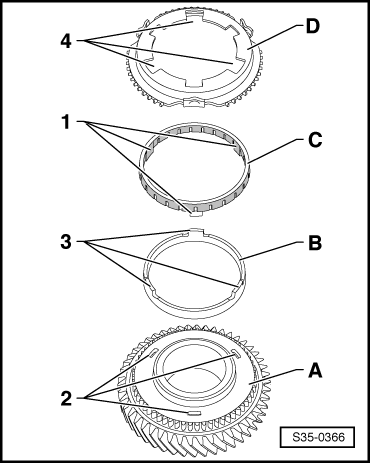
Check the outer friction surface of the intermediate ring for wear
–  Check synchronizer ring -arrow- on the inner friction surface (position to intermediate ring) for scoring and radial bearing marks, replace if necessary.
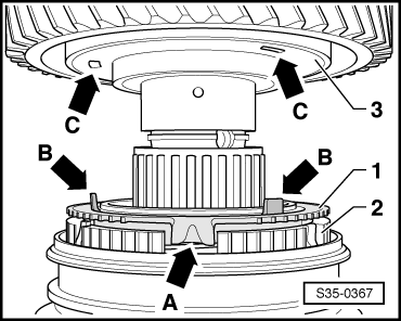
–  Position inner ring, intermediate ring and synchronizer ring in fitting position → Fig. onto the sliding gear and “screw in”.
  Note
“Screw in ” means: Turn synchronizer rings by one revolution while pressing on the rings simultaneously.
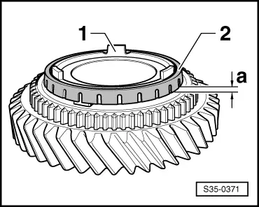
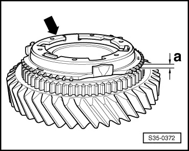
–  Then measure the gap -a- at 3 points, offset by 120°, with a feeler gauge. Note the mean value.
  S35-0372
Clearance -a-Wear limit
1st,2nd and 3rd gear0.8 mm

  Note
t  When measuring, insert the feeler gauge in the area of the synchronizer ring serration.
t  When measuring, do not push the feeler gauge under the intermediate ring, only measure the gap -a- between sliding gear and synchronizer ring.
t  Replace the inner ring, intermediate ring and synchronizer ring together for the relevant gear → Electronic Catalogue of Original Parts.
   

Setting output shaft gears 1 through 4 > < Disassembling and assembling output shaft gears 1 through 4