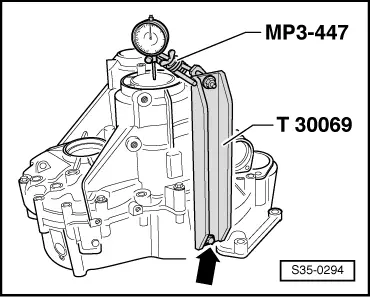
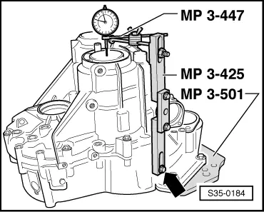
| The supporting bridge -MP3-425- can also be fitted to the clutch housing -arrow-instead of the assembly device -T30069-. |
| –
| Dial gauge (3 mm measuring range) and set to “0” with a 1 mm bias. |
| –
| Slacken fixing screws of clutch housing/gearbox housing crosswise, until the screws release the gearbox housing or the output shaft. |
| –
| Read off measured value on dial gauge and note (example: 0,14 mm). |

Note | If no measured value is displayed on the dial gauge when loosening the fixing screws of the clutch housing/gearbox housing, install the adjusting washer 1.95 mm or if necessary the adjusting washer 2.20 mm for the measurement. |
| Determine the adjusting washer |
| The prescribed bearing preload is reached by removing the established measured value (0,14 mm) from the inserted adjusting washer (1.70 mm) and by adding a constant compression value (0.20 mm). |
|
|
|