| –
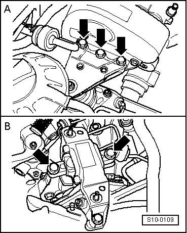
| Secure unit in the engine and gearbox mount -arrows- and tighten the screws to the recommended tightening torque → Chapter. |
| Vehicles fitted with a manual gearbox |
| Continued for all vehicles |
| Vehicles with air conditioning |

Note | To avoid damaging the condenser, wiring and coolant hoses, make sure the lines and hoses are not excessively expanded, buckled or bent. |
| Continued for all vehicles |
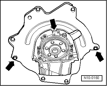
| –
| Install pendulum support and tighten the screws to the prescribed tightening torque → Chapter. |
| –
| Install pre-exhaust pipe: |
| t
| Engines with identification characters AUA, AUB, BBY, BBZ → Chapter |
| t
| Engine with identification characters BKY → Chapter |
| t
| Engine with identification characters BUD → Chapter |
| For engines with identification characters AUA, AUB, BBY, BBZ, BKY |
| –
| Install engine cover with air filter. |
| For engine with identification characters BUD |
| For engines with identification characters BKY up to 05/2005, AUA, AUB, BBY, BBZ |
| Continued for all vehicles |
|
|
|