skoda Workshop Repair Guides

Skoda Workshop Service and Repair Manuals

Securing the engine to the assembly stand > < Removing and installing engine
Removing
Removing
  Note
All cable straps that have been loosened or cut open when the engine was removed must be attached again in the same location when the engine is installed again.
–  First check whether a radio with anti-theft coding has been fitted. If this is the case obtain coding.
–  Disconnect the earth strap from the battery with the ignition off.
–  Remove battery and battery tray → Electrical System; Rep. gr.27.
  WARNING
Observe measures when disconnecting the battery → Electrical System; Rep. gr.27.
–  Disconnect the positive wire from the battery to the starter (is removed together with the unit).
For engines with identification characters AUA, AUB, BBY, BBZ, BKY
   
–  Pull off hose -1- (for engines as of 04/2002) and remove engine cover -2- with air filter upwards -arrows-.
For engine with identification characters BUD
  S15-0259
–  Press the catches -arrows- and pull the inlet connection out of the intake air duct.
–  Release spring strap clamp and disconnect intake hose from air filter housing.
Continued for all vehicles
–  Open cap of expansion reservoir to release pressure in the cooling system.
  N24-10322
–  Release the screws at the noise insulation -arrows- and remove noise insulation.
–  Remove exhaust pipe.
t  Engines with identification characters AUA, AUB, BBY, BBZ → Chapter
t  Engine with identification characters BKY → Chapter
t  Engine with identification characters BUD → Chapter
  S10-0101
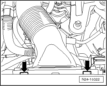
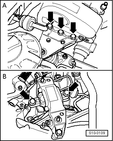
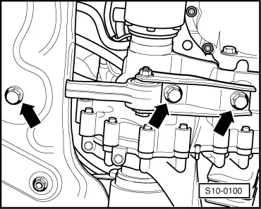
–  Remove pendulum support -arrows-.
–  Unscrew drive shaft to the right and left of the gearbox and tie up → Body; Rep. gr.40.
–  Drain coolant → Chapter.
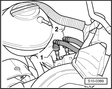
–  Pull off coolant hoses at the top and bottom from the radiator.
  Note
When disconnecting the hoses the residual coolant flows out! Make sure a catch pan is positioned underneath.
–  Disconnect the plug connections on the plug holder below the starter:
t  Plug connection to lambda probe wire
t  Plug connection to AC compressor cable
t  Plug connection to generator cable
–  Disconnect plug connection of the reverse gear switch from the gearbox.
–  Remove front bumper → Body Work; Rep. gr.63.
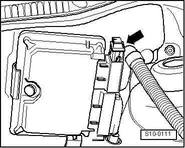
–  Disconnect the following plug connections:
t  Plug connection of the electric wiring to the radiator fans
t  Plug connection of the thermo-switch -F18-
t  Plug connection of the electric wiring to the main headlights and fog lights
Vehicles with air conditioning
  WARNING
Do not open the refrigerant circuit of the air conditioning system. Therefore, when laying aside the lock carrier pay special attention to the air conditioning hoses, that must not be folded or exposed to stress.
  Note
To avoid damaging the condenser, wiring and coolant hoses, make sure the lines and hoses are not excessively expanded, buckled or bent.
–  Unscrew the retaining clips of the refrigerant lines.
–  Remove V-ribbed belt → Chapter.
–  Remove connector from the AC compressor.
–  Remove AC compressor → Heating, Air Conditioning; Rep. gr.87.
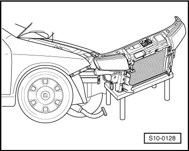
–  Attach the AC compressor to the lock carrier.
Continued for all vehicles
  S10-0100
–  Remove the lock carrier with component parts → Body Work; Rep. gr.50 and lay aside.
–  Unplug connector from the starter.
  S10-0128
–  Disconnect the plug from the engine control unit -arrow-.
–  Disconnect 10-pin plug connection in left of engine compartment and lay wiring loom aside.
  Note
The unit is removed together with the wiring loom.
Vehicles fitted with a manual gearbox
–  Remove shift cables of shift mechanism from gearbox and place down to the side → Gearbox; Rep. gr.34.
–  Remove clutch cylinder and lay aside → Gearbox; Rep. gr.30.
  Note
The clutch pedal must not be depressed.
Vehicles with automatic gearbox
–  Remove selector lever control cable from the gearbox and lay aside → Automatic Gearbox; Rep. gr.37.
Continued for all vehicles
–  Disconnect earth strap of the gearbox.
–  Release spring strap clamps and disconnect hoses of the coolant regulator housing:
t  Inlet hose to heat exchanger for heating
t  Hose of expansion reservoir
t  Return-flow hose from heat exchanger for heating
  Note
When disconnecting the hoses the residual coolant flows out! Make sure a catch pan is positioned underneath.
–  Disconnect the hose of the vent line from the throttle valve.
  S10-0111
–  Detach the fuel feed line -2- and (press the release button) and catch the fuel which flows out with a cleaning cloth.
–  Disconnect the ventilation hose for the coolant expansion reservoir from the ventilation pipe.
–  Remove vacuum hose from the brake servo unit.
  S10-0389
–  Attach the lifting device -MP9-201 (2024 A)- as shown in the illustration and raise slightly with the workshop crane:
t  Belt pulley side: 4th hole of vertical perforated bar in position 1.
t  Flywheel side: 2nd hole of vertical perforated bar in position 8.
  WARNING
Use securing pins on the hooks and rig pins to prevent release.
  Note
t  The hole of the supporting bracket -1- points towards the belt pulley.
t  The holes in the vertical perforated bars are counted from the hook.
  S10-0103
–  Screw out screws -arrows- from engine mount -A- and from gearbox mount -B-.
–  Lower assembly and take out to the front.
  Note
The unit must be guided carefully so as not to damage the body.
  S10-0109

Securing the engine to the assembly stand > < Removing and installing engine