
Fabia Mk1
| Summary of components |
 Note
Note| Mark the rotation direction before removing the V-ribbed belt. Reversing the rotation direction of an already used belt may destroy it. |
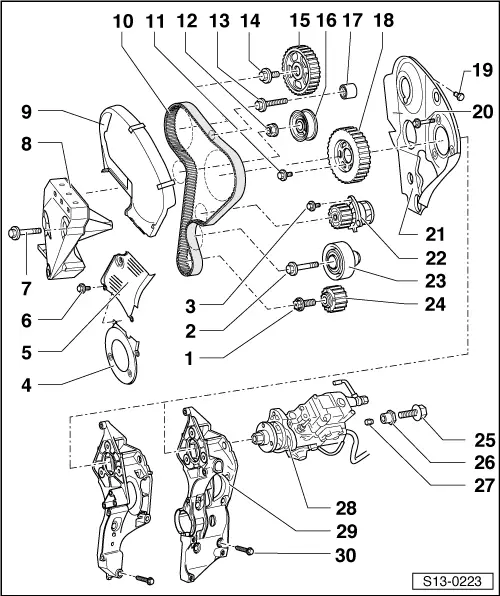
| 1 - | 120 Nm + torque a further 90° (1/4 turn) |
| q | to release and tighten use counterholder -T30004- (place 2 washers underneath) |
| q | replace |
| q | only use the original screw, do not oil or grease |
| 2 - | 40 Nm + torque a further 90° (1/4 turn) |
| q | replace |
| 3 - | 15 Nm |
| 4 - | Bottom toothed belt guard |
| q | remove for removing the vibration dampener |
| 5 - | Middle toothed belt guard |
| 6 - | 10 Nm |
| q | replace |
| 7 - | 45 Nm |
| 8 - | Engine support bracket |
| 9 - | Top toothed belt guard |
| 10 - | Toothed belt |
| q | before removing mark running direction |
| q | check for damage |
| q | do not kink |
| q | removing and installing → Chapter |
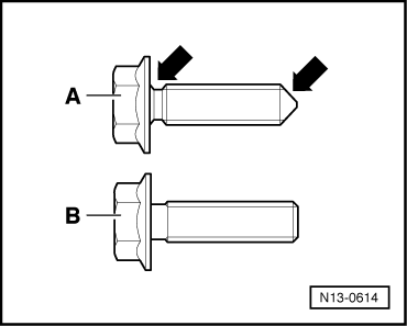
| 11 - | Fixing bolts for the injection pump gear |
| q | pay attention to different versions (part number) and tightening torques → Fig. |
| 12 - | 25 Nm |
| 13 - | 20 Nm |
| 14 - | 45 Nm |
| q | to release and tighten the counterholder -MP1-216- or -T30004- use |
| 15 - | Camshaft sprocket |
| q | remove with extractor -T40001- → Chapter |
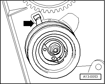
| 16 - | Semi-automatic tensioning pulley |
| q | check → Chapter |
| q | Fitting position → Fig. |
| 17 - | Guide pulley |
| 18 - | Injection pump gear |
| q | pay attention to different versions related to the fixing screws (Pos. 11) → Fig. |
| q | both versions with the relevant bolts may be fitted |
| 19 - | 10 Nm |
| q | replace |
| 20 - | 30 Nm |
| 21 - | Rear toothed belt guard |
| 22 - | Coolant pump |
| q | removing and installing → Chapter |
| 23 - | Guide pulley |
| q | to remove, unscrew the coolant pump |
| 24 - | Crankshaft - toothed belt sprocket |
| q | there must not be any oil present on the contact surface between the toothed belt sprocket and the crankshaft |
| q | Fitting position: flat on timing belt sprocket and crankshaft must be aligned |
| 25 - | 30 Nm |
| 26 - | Bush |
| 27 - | Nut |
| q | slide into the bush Pos. 26 |
| 28 - | Injection pump |
| q | never loosen the central nut |
| q | removing and installing → Chapter |
| q | testing and adjusting commencement of injection → Chapter |
| q | Newly seal injection pump → Chapter |
| 29 - | Support |
| q | different for vehicles with and without air conditioning |
| 30 - | 45 Nm |
|
|