
Fabia Mk1 | 12/40; 47kW MPI engine | Fuel Tank with Parts | Fuel Filter
| For engines with identification characters AZQ, BMD, BME |
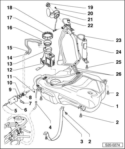
| 1 - | Fuel tank |
| q | support with engine/gearbox jack -V.A.G 1383 A- when removing |
| q | removing and installing → Chapter |
| q | after replacing the fuel tank, bleed → Chapter the fuel supply with the valve on the fuel strip |
| 2 - | 25 Nm |
| 3 - | Tensioning strap |
| 4 - | Vent line |
| q | to solenoid valve 1 for activated charcoal filter -N80- in engine compartment |
| 5 - | Fuel feed line |
| q | black |
| q | to fuel strip at intake manifold |
| 6 - | Fuel filter |
| q | up to 07.02 the filter fitted with the integrated fuel pressure regulator; replace with a new illustrated version when replacing |
| q | pay attention to different connections of fuel line: |
| t | for filter with integrated fuel pressure regulator in the middle black feed line and on the outside blue return-flow line |
| t | for filter with disassembled fuel pressure regulator in the middle blue return-flow line and on the outside black feed line |
| q | as spare parts in the kit with a new gasket ring Pos. 9 and O-ring Pos. 10 |
| q | after replacing the fuel filter, bleed → Chapter the fuel supply with the valve on the fuel strip |
| q | Fitting location: Pin at filter housing must engage in the recess of the guide for the fixing clamp |
| q | the direction of flow is marked by arrow |
| 7 - | Retaining clip |
| q | check for firm seating |
| 8 - | Fuel pressure regulator |
| q | for vehicles manufactured up to 06.06 0.3 MPa (3 bar) |
| q | for vehicles manufactured as of 06.06 0.4 MPa (4 bar) |
| q | as spare parts in the kit with a new gasket ring Pos. 9 and O-ring Pos. 10 |
| 9 - | Sealing ring |
| q | replace |
| 10 - | O-ring |
| q | replace |
| 11 - | 5 Nm |
| q | for collar clamp for fuel filter |
| 12 - | Fuel gauge sender -G- |
| q | removing and installing → Chapter |
| 13 - | Fuel delivery unit |
| q | removing and installing → Chapter |
| q | inspecting fuel pump → Chapter |
| q | Clean strainer if dirty |
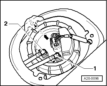
| q | Fitting position of flange of fuel delivery unit → Fig. |
| 14 - | Return-flow line |
| q | up to 07.02 between fuel delivery unit and fuel filter |
| q | as of 08.02 between fuel delivery unit and fuel pressure regulator |
| q | blue |
| 15 - | Feed line |
| q | between the fuel delivery unit and the fuel filter |
| q | black |
| 16 - | Sealing ring |
| q | moisten with fuel before installing |
| 17 - | Union nut |
| q | use wrench for union nut -MP1-227 (3217)- for removing and installing → Chapter |
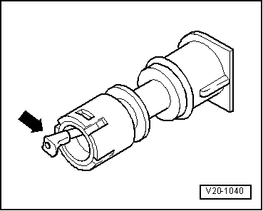
| 18 - | Vent valve |
| q | to remove, unclip valve at side and take out of filler neck. |
| q | before installing, unscrew screw cap Pos. 19 |
| q | check → Fig. |
| 19 - | Screw cap |
| 20 - | 1.5 Nm |
| 21 - | Fuel tank lid unit |
| q | with rubber bowl |
| 22 - | Gravity valve |
| q | to remove, unclip valve at top and lift out of filler neck |
| q | inspect valve for blockage: |
| t | Valve in a vertical position: open |
| t | Valve tilted 45°: closed |
| 23 - | Vent line |
| q | between activated charcoal filter Pos. 24 and vent line Pos. 4 |
| 24 - | Activated charcoal filter |
| 25 - | 10 Nm |
| 26 - | Vent line |
| q | clipped in place on fuel tank |
 Note
Note
|
|