skoda Workshop Repair Guides

Skoda Workshop Service and Repair Manuals

Securing the engine to the assembly stand > < Removing and installing engine
Removing
Removing
  Note
All cable straps that have been loosened or cut open when the engine was removed must be attached again in the same location when the engine is installed again.
–  First check whether a radio with anti-theft coding has been fitted. If this is the case obtain coding.
–  Disconnect the earth strap from the battery with the ignition off.
–  Remove battery and battery tray → Electrical System; Rep. gr.27.
  WARNING
Observe measures when disconnecting the battery → Electrical System; Rep. gr.27.
–  Disconnect the positive wire from the battery to the starter (is removed together with the unit).
   
–  Pull out oil dipstick -1-.
–  Release the nut -2-.
–  Remove engine cover -3- in -direction of arrow-.
–  Remove air filter with connections → Chapter.
  S10-0455
–  Disconnect the plug from the engine control unit -arrow-.
  Note
The unit is removed together with the wiring loom.
–  Separate plug connector from wiring harness in left of engine compartment.
–  Detach engine wiring harness from retaining clips, separate plug connections and place on the engine.
–  In the right of the engine compartment separate the cable from the solenoid valve -N80- and the lambda probe upstream of catalytic converter -G39-.
–  Separate plug connections and cables from alternator (also AC compressor, if fitted) → Electrical System → Rep. gr.27, detach wiring harness from retaining clamps and place onto the body.
–  Open cap of expansion reservoir to release pressure in the cooling system.
–  Drain coolant → Chapter.
–  Pull off coolant hose at the top and bottom of the radiator.
  Note
When disconnecting the hoses the residual coolant flows out! Make sure a catch pan is positioned underneath.
–  Unscrew the screws of the noise insulation and remove the noise insulation.
–  Disconnect plug connection of the reverse gear switch from the gearbox.
–  Disconnect the following plug connections:
t  Plug connection of the wiring to the radiator fans
t  Plug connection of the thermo-switch -F18-
t  Plug connection of the wiring to the main headlights and fog lights
–  Unscrew pre-exhaust pipe from exhaust manifold → Chapter.
  S10-0111
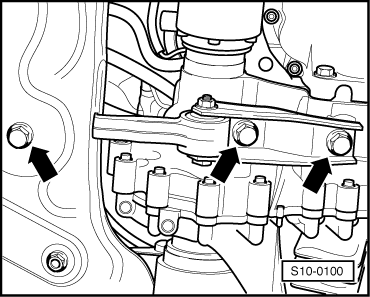
–  Remove pendulum support -arrows-.
–  Unbolt right and left drive shafts from gearbox and tie up at body → Running Gear; Rep. gr.40.
Vehicles with air conditioning
  WARNING
Do not open the refrigerant circuit of the air conditioning system. Therefore, when laying aside the lock carrier pay special attention to the air conditioning hoses, that must not be folded or exposed to stress.
  Note
To avoid damaging the condenser, wiring and coolant hoses, make sure the lines and hoses are not excessively expanded, buckled or bent.
  Note
Observe supplementary instructions and assembly work → Chapter.
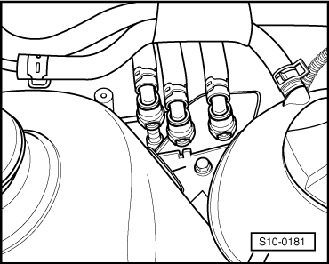
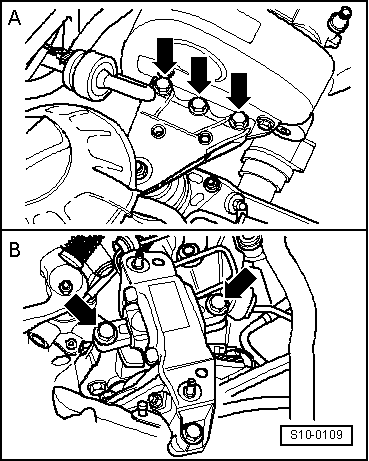
–  Unscrew the retaining clips of the air conditioning lines.
–  Remove V-ribbed belt → Chapter.
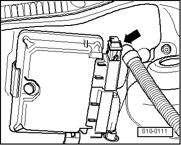
–  Remove connector from the AC compressor.
–  Remove AC compressor → Heating, Air Conditioning; Rep. gr.87.
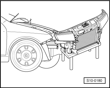
–  Attach the AC compressor to the lock carrier.
Continued for all vehicles
  S10-0100
–  Remove the lock carrier with component parts → Body Work; Rep. gr.50 and lay aside.
–  Unplug connector from the starter.
–  Remove shift cables of shift mechanism from gearbox and place down to the side → Gearbox; Rep. gr.34.
–  Remove slave cylinder from gearbox and place down to the side → Gearbox; Rep. gr.30. Lines remain connected.
  Note
The clutch pedal must not be depressed.
–  Disconnect earth strap of the gearbox.
–  Slacken spring collar clamps and detach the following coolant hoses:
t  Inlet hose to heat exchanger for heating
t  Return-flow hose from heat exchanger for heating
t  Ventilation hose from heat exchanger for heating
t  Return-flow hose from expansion reservoir
t  Ventilation hose from expansion reservoir
  Note
When disconnecting the hoses the residual coolant flows out! Make sure a catch pan is positioned underneath.
  S10-0180
–  Detach fuel feed, fuel return-flow and fuel vent lines.
  WARNING
The fuel line is under pressure! Place clean cleaning cloths around the connection point before detaching hose connections. Reduce pressure by carefully removing the hose.
–  Allow coolant vent hose and fuel vent hose to hang freely at the assembly together with solenoid valve -N80-.
–  Remove vacuum hose from the brake servo unit.
  S10-0181
–  Attach lifting device -MP9-201 (2024 A)- as shown in the figure and raise slightly using the workshop crane.
t  Belt pulley side: 3rd hole of vertical perforated bar in position 2.
t  Flywheel side: 3rd hole of vertical perforated bar in position 8.
  WARNING
Use securing pins on the hooks and rig pins to prevent release.
  Note
t  The hole of the supporting bar points toward the belt pulley.
t  The holes in the vertical perforated bars are counted from the hooks.
  S10-0095
–  Screw out screws -arrows- from engine mount -A- and from gearbox mount -B-.
–  Lower assembly and take out to the front.
  Note
The unit must be guided carefully so as not to damage the body.
  S10-0109

Securing the engine to the assembly stand > < Removing and installing engine