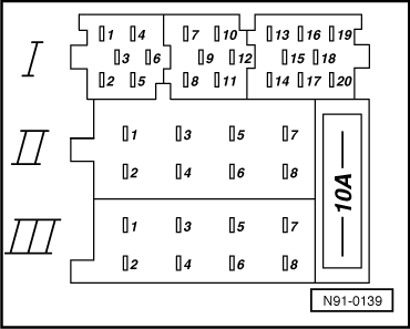
| Multipin plug connection I, part 1, yellow |
| 1 - | Line Out rear left, LR |
| 2 - | Line Out rear right, RR |
| 4 - | Line Out left front, LF |
| 5 - | Line Out right front, RF |
| 6 - | Switched positive for sound amplifier |
| Multipin plug connection I, part 2, green |
| 7 - | Telephone input signal, TEL+ |
| 8 - | Second display, CLOCK |
| 12 - | Telephone input signal, TEL- |
| Multipin plug connection I, part 3, blue |
| 14 - | CD changer, DATA OUT |
| 16 - | CD changer, voltage supply (+), terminal 30 |
| 17 - | CD changer, control signal |
| 18 - | CD changer, left and right channel, earth |
| 19 - | CD changer, left channel, CD/L |
| 20 - | CD changer, right channel, CD/R |
| Multipin plug connection II, -T8a-, 8-pin, brown |
| 3 - | Speaker + front right |
| 4 - | Speaker - front right |
| Multipin plug connection III, -T8a-, 8-pin, black |
| 1 - | Gala (volume adaptation depending on vehicle speed) |
| 2 - | Mute (telephone mode) |
| 3 - | Self-diagnosis/K wire |
| 4 - | Connection for ignition key-controlled On / Off |
| 5 - | Terminal 30 - Anti-theft lock control signal, SAFE |
|
|
|
