skoda Workshop Repair Guides

Skoda Workshop Service and Repair Manuals

Removing and installing parts of the ESP System > < Removing and installing the ABS speed sensor on the rear axle
Repairing rear ABS speed sensor cables - Vehicles with ABS BOSCH 8.0
Special tools and workshop equipment required
t  Wiring loom repair kit, e.g. Skoda Car Tool Kit Škoda, Order No.: -S 504 500 V-
t  Vehicle diagnosis, measurement and information system -VAS-
  Note
The procedure for repairing the ABS speed sensor cables is identical for vehicles with drum brakes and for vehicles with disc brakes.
Removing:
–  Disconnect battery → Electrical System; Rep. gr.27.
–  Release plug connection on wheel speed sensor and separate plug connector.
–  Unclip wheel speed sensor cable on rear axle and body.
–  Removing the seat bench → Body Work; Rep. gr.72.
–  Removing trim panel at bottom of pillar C → Body Work; Rep. gr.70.
–  Removing the entrance plate → Body Work; Rep. gr.68.
–  Fold back the floor covering around the seat bench.
   
–  Release the rubber grommet -1- and pull the wheel speed sensor cable -2- into the vehicle interior.
–  Separate the ABS speed sensor cable between crimp connection -arrow A- and sheathing -arrow B-.
Installing:
–  Draw in the new wheel speed sensor cable and attach the rubber grommet.
–  Insulate the two cable extremities with a 6...7 mm wire stripper.
–  Twist the two cable extremities.
  Note
t  The insulation of the cable extremities must not be twisted.
t  Make sure the correct red crimp connector for 0.5 mm 2 is selected.
  S45-0080
–  Slide the crimp connector on the cable extremities and crimp together at both sides with the pliers.
  Note
t  The crimp connector must be heated from the centre towards the outside until it is fully sealed and the adhesive flows out.
t  Set the hot-air blower to the relevant temperature according to the operating instructions.
t  When heating up the crimp connector, make sure the hot nozzle does not damage any other cables, plastic parts or insulating materials.
  S45-0081
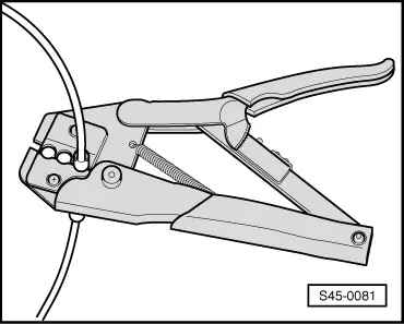
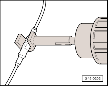
–  After pressing on, the crimp connector must be heated with the hot-air blower.
   To do so use the hot-air blower from the wiring loom repair kit.
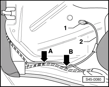
–  If the repair cable was initially insulated, this point must be rewrapped with yellow insulating tape, or if necessary the cable must be attached again with a cable strap.
Further installation occurs in reverse order.
–  Installing the entrance plate → Body Work; Rep. gr.68.
–  Installing trim panel at bottom of pillar C → Body Work; Rep. gr.70.
–  Installing the seat bench → Body Work; Rep. gr.72.
  Note
Pay attention to the measures after re-connecting the battery → Electrical System; Rep. gr.27.
–  Connect battery → Electrical System; Rep. gr.27.
–  Perform vehicle system test with vehicle diagnosis, measurement and information system -VAS- → Chapter.
  S45-0202

Removing and installing parts of the ESP System > < Removing and installing the ABS speed sensor on the rear axle