skoda Workshop Repair Guides

Skoda Workshop Service and Repair Manuals

Removing and installing outer joint of the drive shaft (as of CW 12 2008) > < Removing and installing nut for securing the drive shaft
Removing and installing outer joint of the drive shaft (up to CW 11 2008)
Special tools and workshop equipment required
t  Extractor -MP6-425 (3283)-
t  Polycarbamide grease -G 052 142 A2-
Removing:
–  Unscrew twelve-point nut from the drive shaft → Chapter.
–  Remove front wheel.
  Note
When replacing the track control arm -2- or the steering joint -1- the installation position of the screws for the steering joint -arrows- to the track control arm and the installation position of the steering joint to the track control arm are not marked.
   
–  Mark fitting position of screws -arrows- from steering joint -1- to track control arm -2-.
–  Mark installation position of the steering joint -1- for the track control arm -2-.
–  Release screws -arrows-.
–  Slide the steering joint -1- with wheel-bearing housing out of the bottom track control arm -2-
–  Swivel out the wheel-bearing housing with the suspension strut and simultaneously take the drive shaft out of the wheel-bearing housing. Tie up drive shaft.
  Note
t  The drive shaft must not hang down! The inner joint can be damaged by excessive offset.
  S40-0338
t  
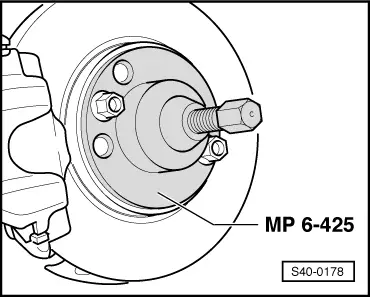
If the drive shaft cannot be pulled out of the wheel-bearing housing, e.g. for removal use the extractor -MP6-425 (3283)-
Installing:
  Note
Remove possible corrosion and grease residue from the thread and from the serration of the outer joint as well as from the serration of the wheel-bearing housing.
–  Grease the serration on the propeller shaft with polycarbamide grease -G 052 142 A2-.
   Do not grease thread on the outer joint of the drive shaft.
–  Grease the serration in the wheel-bearing housing with polycarbamide grease -G 052 142 A2-.
  S40-0178
–  Swivel out the wheel-bearing housing with the suspension strut and push the drive shaft joint into the serration of the wheel-bearing housing. Insert the steering joint -1- at the same time into the bottom track control arm -2-.
–  Secure the outer joint of the drive shaft with a new twelve-point nut.
  Note
Use new screws and new lock washer to screw the steering joint/track control arm.
  S40-0338
–  Position the track control arm -2- and steering joint -1- relatively to each other in such a way that the holes -arrows- of the track control arm and steering joint are flush.
For better fixing use two drifts with a Ø 8.3 mm or two drill bits also with a Ø 8.3 mm.
  S40-0337
–  Screw the track control arm -2- and the steering joint -1- with the new screws -arrows- and new lock washer and tighten (for „marked fitting position“ see removal - tighten in the marked fitting position).
  Note
Make sure the steering joint boot is neither damaged nor twisted.
–  Tighten new twelve-point nut for securing the drive shaft → Chapter
–  Tighten wheel.
–  Perform a test drive.
  Caution
If after the test drive and with the front wheels pointing straight ahead the steering wheel is off straight, perform a chassis alignment → Chapter.
  S40-0338
Tightening torques:
Twelve-point nut for securing the drive shaft to wheel hub
t  Use new nut!
t  Do not grease thread of the outer joint of the drive shaft.
50 Nm + 45°
Steering joint to track control arm
t  Use new screws!
t  Use new lock washer!
20 Nm + 90°
Wheel bolts → Chapter


Removing and installing outer joint of the drive shaft (as of CW 12 2008) > < Removing and installing nut for securing the drive shaft