| –
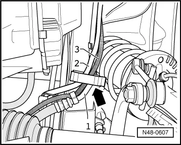
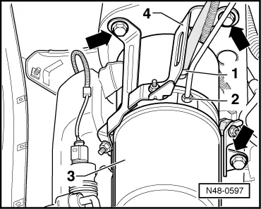
| Open the spring strap clamp -1- with assembly pliers and carefully pull off the return line from the support of the engine pump aggregate -3-. |
| –
| Unscrew pipe screw -2- from the engine pump aggragate and pull out the pressure line. |
| –
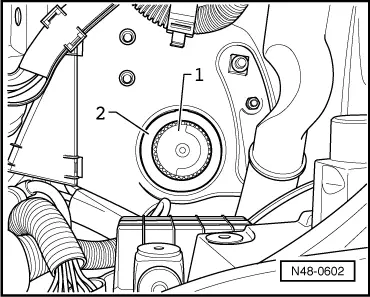
| Close the threaded bores -2- and supports -1- on the engine pump aggregate. |
| –
| Lower the assembly carrier in the service position (depending upon the vehicle version - axle up to CW 11 2008 → Chapter or axle as of CW 12 2008 → Chapter). |

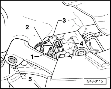
Caution | When lowering the assembly carrier with the power steering, make sure the pressure line (expansion hose), return hose and the line of the power-steering sensor -G250- are not exposed to traction. |
|
| –
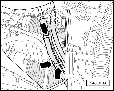
| Lowering assembly carrier with power-assisted steering gear. |
|
|
|

 Note
Note