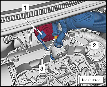
skoda Workshop Repair Guides

Skoda Workshop Service and Repair Manuals

Removing and installing the fuel distributor > < Installing the high pressure lines
Removing and installing the injection units
Special tools and workshop equipment required
t  Extractor -T10055-
t  Assembly sleeve -T10377-
t  Socket wrench insert -T40055-
t  Assembly sleeve -T10411-
t  Extractor -T10426-
Removing
Observe safety measures and rules of cleanliness when undertaking all work on the fuel system → Chapter.
–  Remove engine cover → Chapter.
   
–  Disconnect plug -1- from position sender for charge pressure regulator -G581-.
  Caution
Pay attention to cleanliness.
l  Under no circumstances dirt must get into the removed return lines and the connections of the injection units.
l  It is absolutely necessary to protect the opened fuel connections from dirt with suitable means.
  N23-10377
–  Detach the return-flow line connections. To do so, release the catch -1-.
–  Detach the fuel return-flow lines from the injection units to be removed in -direction of arrow-.
  N23-10353
–  Disconnect the plug -1- at the injection units to be removed.
–  Replace the connector gasket ( → Chapter, Pos. 4) of the connectors -1- → Electronic Catalogue of Original Parts.
–  Remove high pressure lines between fuel distributor and injection units to be removed.
  N23-10352
–  Release the screw of the clamping claw for the injection unit to be removed.
  Caution
Pay particular attention in order to avoid unnecessary installation work or consequential damage.
  N23-10356
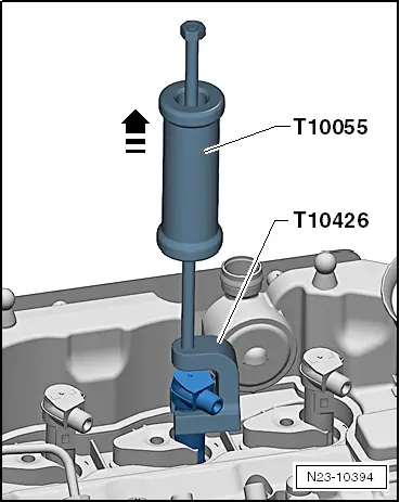
–  Position the extractor -T10055- with the extractor -T10426- as shown.
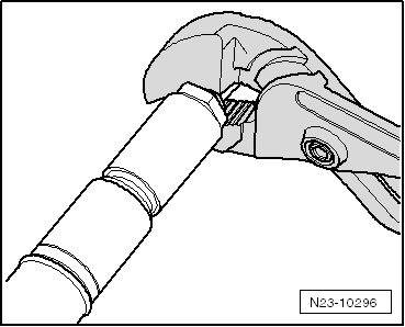
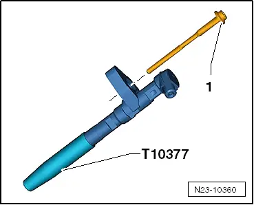
–  Always pull out the injection unit together with the clamping claw towards the top by tapping it.
  Note
Place the removed injection units on a clean cloth.
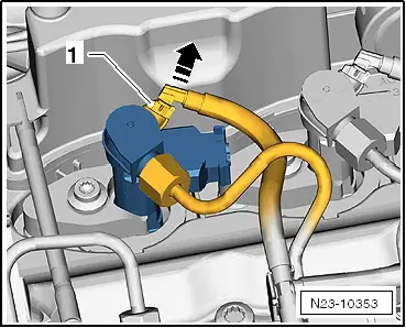
–  Remove the soot particles on the sealing surface of the injection unit in the cylinder head and the dirt in the opening with a cloth soaked in engine oil or in rust solvent, if necessary.
  Caution
Make sure the sealing surfaces are not damaged in the process.
Important instructions for the replacement of parts
When reinstalling the injection unit, the following parts must be replaced:
t  Copper seal
t  O-ring of bore for injection unit
t  Screw for clamping claw
When installing the new injection unit, the following must also be replaced:
t  Clamping claw
t  Injection unit for cylinder
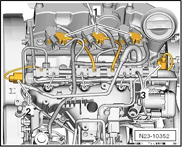
Instructions for reinstalling the injection units
  Note
t  When reinstalling, the injection units, the injection lines and the clamping claws must only be installed at the same point where they were removed.
t  The reinstalled injection units or injection lines must not be damaged.
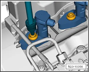
–  Spray the tip of the injection unit with a rust solvent spray. Remove the soot and grease particles with a cloth after approx. 5 minutes.
  N23-10394
–  Remove the old copper seal from the injection unit; to do so, carefully tighten the copper seal with pliers until the copper seal does no longer turn. Then pull the injection unit out of the copper seal with slight turning and pulling movements of the hand.
l  Check the injection units and the fitting positions for cleanliness before installing.
Mounting sequence
  Note
All the O-rings must be coated with engine oil before installing.
–  Insert a new copper seal on the injection unit with plastic bushing.
  N23-10296
–  Replace the gasket ring of the bore for the injection unit, for this step use the assembly sleeve -T10377-.
–  Slide the clamping claw onto the injection unit. Check fitting position → Chapter.
–  Carefully insert the injection unit with the clamping claw into the bore in the cylinder head.
  Caution
Pay particular attention in order to avoid unnecessary installation work or consequential damage.
–  Screw in the new screw of the clamping claw and first tighten only by hand.
  Note
For a tension-free installation of the injection line, it is essential to align the position of the injection unit by twisting.
–  Install high pressure lines → Chapter.
Further assembly occurs in reverse order.
–  Check gasket rings of fuel return-flow lines for wear, if necessary replace → Chapter.
–  Carefully press the connections of the return-flow lines into the injection units.
l  The cap must click audibly into place.
  Note
After replacing the injection units, carry out „Adaptation of correction values“ in the „Targeted functions“ → Vehicle diagnostic tester.
–  Check fuel system for tightness → Chapter.
  N23-10360

Removing and installing the fuel distributor > < Installing the high pressure lines