
Fabia Mk2
| Parts of the lubrication system - Summary of components |
 Note
Note| t | If considerable quantities of metal swarf or abrasion is found in the engine oil when carrying out engine repairs, carefully clean the oil galleries in order to avoid consequential damage and additionally replace the oil cooler. |
| t | Testing oil pressure and oil pressure switch → Chapter. |
| t | The oil level must not exceed the „max“ marking - risk of damage to catalytic converter! |
| Check the engine oil, amount of oil and oil specification: |
| t | → BookletFabia II. |
| t | → BookletRoomster. |
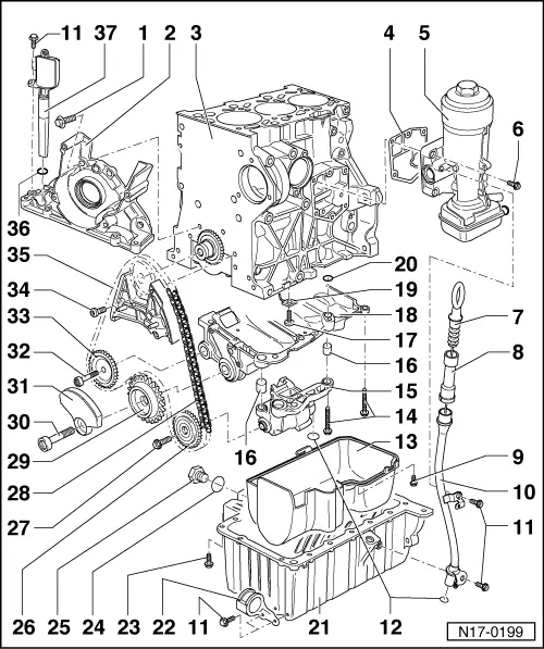
| 1 - | 15 Nm |
| 2 - | Sealing flange -on the belt pulley side- |
| q | with gasket |
| q | must be positioned on dowel sleeves |
| q | removing and installing → Chapter |
| q | install with silicone sealant -D 176 404 A2- → Chapter |
| q | Neither oil nor grease sealing lip of sealing ring |
| q | before installing remove oil residues on crankshaft journal with a clean cloth |
| q | replace the gasket ring for the crankshaft - on the belt pulley side → Chapter |
| 3 - | Cylinder block |
| 4 - | Gasket |
| q | replace |
| 5 - | Oil filter holder |
| q | disassembling and assembling → Chapter |
| 6 - | 15 Nm + torque a further 90° (1/4 turn) |
| q | replace |
| q | first of all set up the bolt at the top left and the bottom right and then tighten all four bolts cross-wise |
| 7 - | Dipstick |
| q | Oil level must not exceed the max. marking |
| 8 - | Filler funnel |
| q | Remove for extracting oil |
| 9 - | 5 Nm |
| 10 - | Guide tube |
| 11 - | 10 Nm |
| 12 - | O-ring |
| q | replace |
| q | check tightness |
| q | lightly oil for assembly |
| 13 - | Cover |
| q | with sealing tape |
| q | Clean strainer if dirty |
| 14 - | 20 Nm |
| 15 - | Oil pump |
| q | with pressure relief valve 11.5 bar (1.15 MPa) |
| q | Before installing, check whether both dowel sleeves are present |
| 16 - | Fitting sleeve |
| 17 - | 25 Nm |
| q | replace without sealant |
| 18 - | Retaining frame |
| q | before assembly, check whether the dowel sleeve is present in the cylinder block and the O-ring is seated in the retaining frame |
| q | removing and installing → Chapter |
| 19 - | Oil injection nozzle |
| q | for piston cooling |
| q | Observe fitting position: turn oil injection nozzle anti-clockwise up to the stop in the cylinder block and tighten in this position |
| 20 - | O-ring |
| q | replace |
| 21 - | Oil pan |
| q | clean sealing surface before installing |
| q | install with silicone sealant -D 176 404 A2- → Chapter |
| q | for removing the oil pan, turn the crankshaft and observe the flywheel, until it faces with the recess downwards |
| 22 - | Support |
| q | for bottom charge-air pipe |
| 23 - | 15 Nm |
| q | Turn the crankshaft and observe the flywheel, until it faces with the recess downwards, so that the rear screws for the gearbox can be removed. |
| 24 - | Sealing ring |
| q | Component part of the drain plug |
| 25 - | Drain plug, 30 Nm |
| q | with integrated gasket ring |
| q | replace |
| 26 - | Sprocket |
| q | for oil pump |
| q | can be installed only in one position |
| 27 - | 20 Nm + torque a further 90° (1/4 turn) |
| q | replace |
| 28 - | Chain |
| q | pay attention to correct installation position → Chapter |
| 29 - | Sprocket |
| q | for balancing shaft |
| q | can be installed only in one position |
| 30 - | 100 Nm + torque a further 90° (1/4 turn) |
| q | replace |
| q | tightening may occur in successive stages |
| 31 - | Balancing weight |
| q | can be installed only in one position |
| 32 - | 20 Nm |
| 33 - | Chain sprocket for guide pulley |
| 34 - | 8 Nm + torque a further 90° (1/4 turn) |
| q | replace |
| 35 - | Chain tensioner with tensioning rail |
| q | to remove lock with -T10060A- |
| q | removing and installing → Chapter |
| 36 - | O-ring |
| q | replace |
| 37 - | Oil level and oil temperature sender -G266- |
| q | check → Vehicle diagnostic tester |