
Octavia Mk1
 Note
Note
|
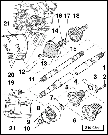
| 1 - | Right joint boot (tubular shaft) |
| t | Assignment → Electronic Catalogue of Original Parts |
| 2 - | Fillister head screw with internal serrations |
| t | replace after each removal |
| t | initially tighten to 10 Nm, subsequently tighten crosswise to final torque: |
| M8 x 48 = 20 Nm + 180° |
| M10 x 52 = 50 Nm + 45° |
| t | Assignment → Electronic Catalogue of Original Parts |
| 3 - | Shim |
| t | Assignment → Electronic Catalogue of Original Parts |
| 4 - | Open warm-type clamp |
| t | replace |
| t | tensioning → Fig. |
| 5 - | Joint boot for inner CV joint, Ø 94 mm |
| t | inspect for tears and chafing points |
| t | remove from CV joint with drift |
| t | The fitting position of the joint boot for the inner CV joint for the right shaft is the same as the fitting position of the joint boot for the outer CV joint Ø 84mm → Fig. |
| t | before installation coat the inside of the cap with sealant -D 454 300 A2- |
| t | Assignment → Electronic Catalogue of Original Parts |
| 6 - | Joint boot for inner CV joint, Ø 100 mm |
| t | inspect for tears and chafing points |
| t | remove from CV joint with drift |
| t | Fitting position for the left shaft → Fig. |
| t | Fitting position for the right shaft → Fig. |
| t | before installation coat the inside of the cap with sealant -D 454 300 A2- |
| t | Assignment → Electronic Catalogue of Original Parts |
| 7 - | Disc spring |
| t | Fitting position → Fig. |
| 8 - | Inner CV joint |
| t | must be replaced completely |
| t | pressing out → Fig. |
| t | pressing on → Fig. |
| t | grease → Anchor |
| t | check → Chapter |
| t | Assignment → Electronic Catalogue of Original Parts |
| 9 - | Gasket |
| t | The adherend on the inner CV joint must be free of grease and oil! |
| t | replace |
| t | Remove the protective foil from the gasket and stick it into the inner joint |
| t | Assignment → Electronic Catalogue of Original Parts |
| 10 - | Circlip |
| t | replace |
| t | remove with circlip pliers, e.g. -VW 161 A-, |
| t | Assignment → Electronic Catalogue of Original Parts |
| 11 - | Left drive shaft (solid shaft) |
| t | Assignment → Electronic Catalogue of Original Parts |
| 12 - | Open warm-type clamp |
| t | replace |
| t | tensioning → Fig. |
| 13 - | Joint boot for outer CV joint |
| t | inspect for tears and chafing points |
| t | Assignment → Electronic Catalogue of Original Parts |
| t | pay attention to different version: Ø 84 mm, Ø 90 mm |
| t | The fitting position of the joint boot for the outer CV joint Ø 90 mm for the left shaft → Fig. |
| t | The fitting position of the joint boot for the outer CV joint Ø 90 mm for the right shaft is determined by the fitting position on the shaft, identical as → Fig. |
| t | The fitting position of the joint boot for the outer CV joint Ø 84 mm for the left shaft → Fig. |
| t | The fitting position of the joint boot for the outer CV joint Ø 84 mm for the right shaft → Fig. |
| 14 - | Open warm-type clamp |
| t | replace |
| t | tension with tensioning pliers, e.g. -V.A.G 1682-, → Fig. |
| 15 - | Disc spring |
| t | Fitting position → Fig. |
| 16 - | Thrust ring |
| t | Fitting position → Fig. |
| 17 - | Circlip |
| t | replace |
| t | insert into the groove at the shaft |
| 18 - | Outer CV joint |
| t | must be replaced completely |
| t | removing → Fig. |
| t | install: drive onto the shaft with a plastic hammer until the compressed circlip expands |
| t | grease → Anchor |
| t | check → Chapter |
| 19 - | 22 Nm |
| 20 - | M8 = 20 Nm, M10 = 33 Nm |
| 21 - | Protective housing |