
Octavia Mk1
 Note
Note
|
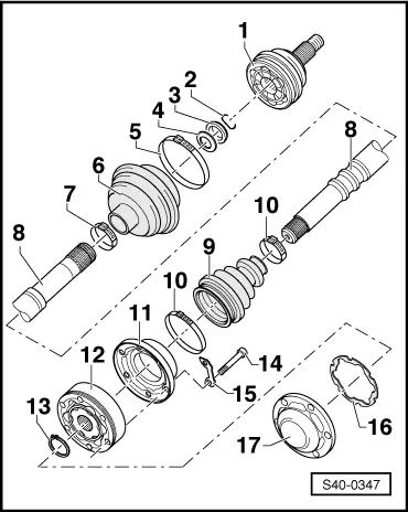
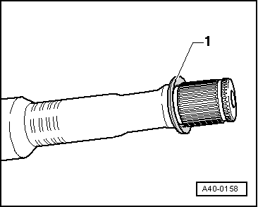
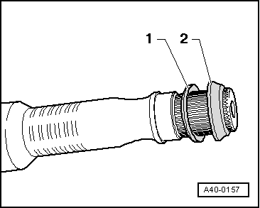
| 1 - | Outer CV joint |
| t | must be replaced completely |
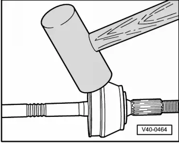
| t | removing → Fig. |
| t | install: drive onto the shaft with a plastic hammer until the compressed circlip expands |
| t | grease → Anchor |
| t | check → Chapter |
| 2 - | Circlip |
| t | replace |
| t | insert into the groove at the shaft |
| 3 - | Thrust ring |
| t | Fitting position → Fig. |
| 4 - | Disc spring |
| t | Fitting position → Fig. |
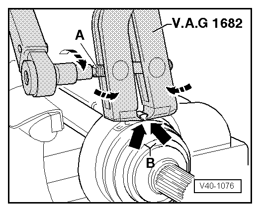
| 5 - | Open warm-type clamp |
| t | replace |
| t | tension with tensioning pliers, e.g. -V.A.G 1682-, → Fig. |
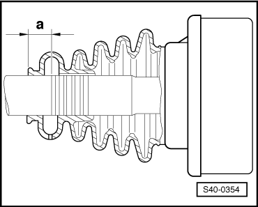
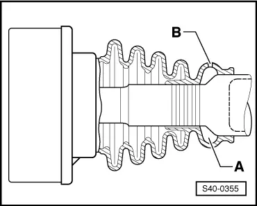
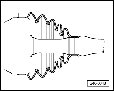
| 6 - | Joint boot for outer CV joint |
| t | Material: Hytrel (Polyelastomere) |
| t | inspect for tears and chafing points |
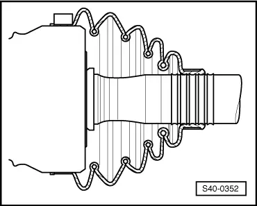
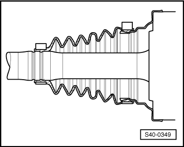
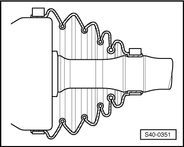
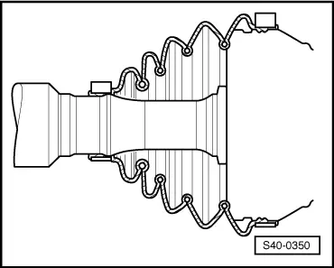
| t | Fitting position for the left shaft → Fig. |
| t | Fitting position for the right shaft → Fig. |
| t | Assignment → Electronic Catalogue of Original Parts |
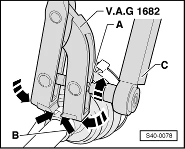
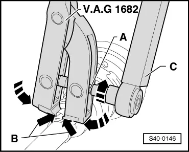
| 7 - | Open warm-type clamp |
| t | replace |
| t | tensioning → Fig. |
| 8 - | Drive shaft |
| t | Assignment → Electronic Catalogue of Original Parts |
| 9 - | Joint boot for inner CV joint |
| t | Material: Arnitel (Polyelastomere) |
| t | inspect for tears and chafing points |
| t | Fitting position for the left shaft → Fig. |
| t | Fitting position for the right shaft → Fig. |
| t | Assignment → Electronic Catalogue of Original Parts |
| 10 - | Open warm-type clamp |
| t | replace |
| 11 - | Cover |
| t | remove from CV joint with drift |
| t | before installation coat the sealing surface of the cap with sealant -D 454 300 A2- |
| t | The sealing surface must be free of oil and grease! |
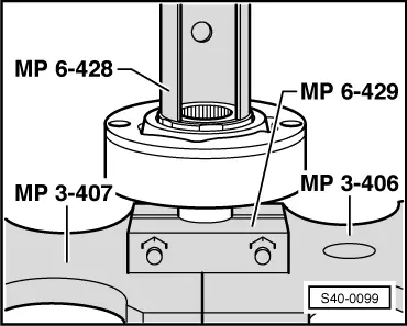
| 12 - | Inner CV joint |
| t | must be replaced completely |
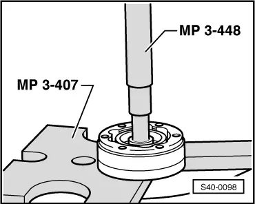
| t | pressing out → Fig. |
| t | pressing on → Fig. |
| t | grease → Anchor |
| t | check → Chapter |
| t | Assignment → Electronic Catalogue of Original Parts |
| 13 - | Circlip |
| t | replace |
| t | remove with circlip pliers, e.g. -VW 161A-, |
| 14 - | Fillister head screw with internal serrations |
| t | replace after each removal |
| t | initially tighten to 10 Nm, subsequently tighten crosswise to final torque: |
| M8 x 48 = 20 Nm + 180° |
| M10 x 52 = 50 Nm + 45° |
| t | Assignment → Electronic Catalogue of Original Parts |
| 15 - | Shim |
| t | Assignment → Electronic Catalogue of Original Parts |
| 16 - | Gasket |
| t | The adherend on the inner CV joint must be free of grease and oil! |
| t | replace |
| t | Remove the protective foil from the gasket and stick it into the inner joint |
| t | Assignment → Electronic Catalogue of Original Parts |
| 17 - | Cover |
| t | remove from CV joint with drift |
| t | before installation coat the sealing surface of the cap with sealant -D 454 300 A2- |
| t | The sealing surface must be free of oil and grease! |
Note
|
|
|
Note
|
|
|
|
|
|
Note
|
|
|
|
Note
|
|
|
|
|
|
|
|
Note
|
|
|
|
|
|
|
|