
Octavia Mk1
 Note
Note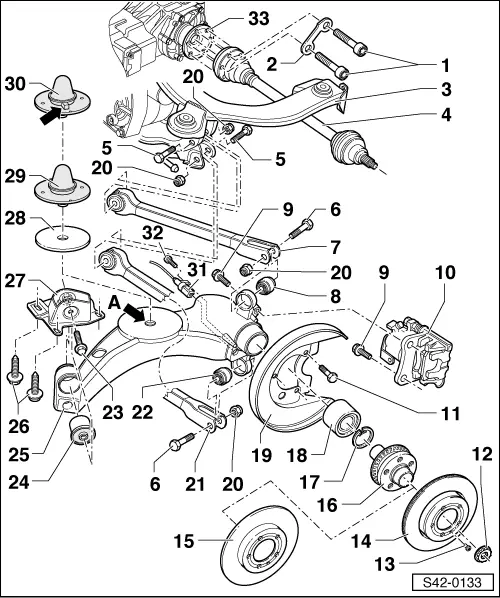
| 1 - | 39 Nm |
| t | replace after each removal |
| t | initially tighten crosswise to 10 Nm, then tighten crosswise to the recommended tightening torque |
| 2 - | Shim |
| 3 - | Assembly carrier |
| t | removing and installing → Chapter |
| 4 - | Drive shaft with inner CV joint |
| t | removing and installing → Chapter |
| t | repairing → Chapter |
| 5 - | 70 Nm + 90° |
| t | M12 x 1.5 x 80 |
| t | replace after each removal |
| 6 - | Screw |
| t | M12 x 1.5 x 75 |
| t | replace after each removal |
| 7 - | Top suspension arm |
| t | removing and installing → Chapter |
| t | different versions, assignment → Electronic Catalogue of Original Parts |
| 8 - | Guide joint |
| t | removing and installing → Chapter |
| 9 - | Collar screw, 80 Nm |
| 10 - | Brake carrier with brake caliper |
| t | repairing → Chapter |
| t | Removing and installing brake pads → Chapter |
| 11 - | 10 Nm |
| 12 - | Self-locking twelve-point nut |
| t | tighten → Chapter |
| t | replace after each removal |
| 13 - | 4 Nm |
| 14 - | Brake disc |
| t | Assignment → Electronic Catalogue of Original Parts |
| 15 - | Brake disc, internally ventilated |
| t | Assignment → Electronic Catalogue of Original Parts |
| 16 - | Wheel hub with pulse rotor for wheel speed sensor |
| t | The pulse rotor is welded with the wheel hub |
| t | Check axial run-out of pulse rotor → Chapter |
| t | pressing in and pressing out → Chapter |
| 17 - | Circlip |
| t | replace after each removal |
| t | pay attention to correct position |
| 18 - | Wheel bearing |
| t | pressing in and pressing out → Chapter |
| t | replace, is damaged when pressing out |
| t | The spare part only as a set „wheel bearing with mounting parts“ (- Pos. 12 and - Pos. 17) |
| 19 - | Cover plate |
| 20 - | Self-locking nut, 70 Nm + 90° |
| t | replace after each removal |
| 21 - | Bottom suspension arm |
| t | removing and installing → Chapter |
| t | Assignment → Electronic Catalogue of Original Parts |
| 22 - | Guide joint |
| t | removing and installing → Chapter |
| 23 - | 90 Nm |
| t | replace after each removal |
| t | insert from the outside of the vehicle |
| 24 - | Rubber-metal bearing |
| t | for trailing arm |
| t | removing and installing → Chapter |
| 25 - | Trailing arm |
| t | removing and installing → Chapter |
| t | The thread -arrow A- for the support of the stop buffer - Pos. 29 is no longer applicable as of 08.99 |
| t | if it is intended to install the stop buffer - Pos. 30 in the trailing arm before the manufacturing date 08.99, the thread -arrow A- must be bored out to Ø 10.5 mm |
| 26 - | 75 Nm |
| t | replace after each removal |
| 27 - | Mount for rear axle |
| t | check the overall track of the rear axle after installation and adjust if necessary |
| t | the track can be corrected by moving the mounting bracket |
| 28 - | Spacer |
| t | only on vehicles with rough road suspension |
| t | on vehicles without spacer, none must be subsequently fitted |
| 29 - | Stop buffer with threaded pin, 10 Nm |
| t | is no longer inserted as of 08.99 |
| t | the stop buffer is delivered as a spare part - Pos. 30 |
| 30 - | Stop buffer with positioning pin |
| t | as of 08.99 |
| t | the correct installation position is determined by the positioning pin |
| t | the positioning pin must be removed on the underside when using vehicles produced before 08.99 |
| t | The beginning of the spring coil must lie against the leg -arrow- |
| t | Fitting position of the coil spring → Chapter and → Chapter |
| 31 - | Wheel speed sensor |
| t | removing and installing → Chapter |
| t | insert with solid lubricant paste -G 000 650- (e.g. Wolfrakote Top Paste) |
| 32 - | 8 Nm |
| 33 - | Flange shaft of the rear axle gearbox |