skoda Workshop Repair Guides

Skoda Workshop Service and Repair Manuals

Removing and installing rubber-metal bearing for trailing arm > < Trailing arm and suspension arm - Summary of components
Pressing out and pressing in
Special tools and workshop equipment required
t  Gearbox jack with adapter, e.g. -V.A.G 1383 A- with -V. A. G 1359/2-
t  Foot pump with high-pressure hose, e.g. -V.A.G 1389 A/1- (Paschke)
t  Hydraulic removal and installation device for wheel bearing, e.g. -V.A.G 1459 B- (Paschke)
with the following individual tools:
t  Hollow piston cylinder, e.g. -HKZ-15-, with pressure plate, e.g. -E-0-204T-
t  Tie bolt, e.g. E-0-217 + 218
t  Special nut, e.g. -E-8-214-
t  Pressure plate, e.g. -E-5-
t  Centering with clamp, e.g. -E-76-2-
t  Supplementary kit, e.g. -V.A.G 1459 B/2-
with the following individual tools:
t  Pressure bushing, e.g. -E-44-
t  Bell, e.g. -E-40-
t  Pressure plate, e.g. -E-6-1-
t  Pressure plate, e.g. -E-13-1-
t  Thrust washer, e.g. -E-39- (-VAS 5146-)
t  
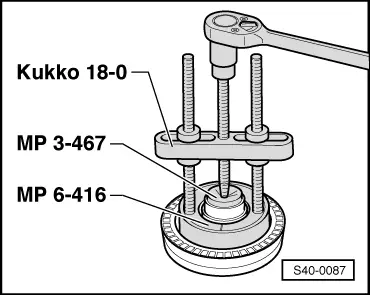
Thrust plate -MP 3-467-
t  Washer -MP 6-416-
t  Extractor -Kukko 18-0-
–  Raise vehicle.
–  Remove wheel.
–  Removing drive shaft → Chapter
   
–  Unscrew fixing screws -1- from brake carrier and remove brake carrier with brake caliper.
  Note
Top fixing screw of the brake carrier covered.
–  Tie brake caliper to the body. The brake line must not be exposed to tension.
–  Screw out the Phillips head screws of the brake disc and remove brake disc.
–  Remove the ABS wheel speed sensor from the trailing arm housing → Chapter.
Press out the wheel hub
  S42-0091
–  Insert the thrust washer -1-.
Position the thrust washer -1- in such a way that it rests fully on the screw heads -2-.
1 - Thrust washer, e.g. -E-39- (-VAS 5146-)
  N42-0389
–  Mount centering with clamp, e.g. -E-76-2-.
1 - Hollow piston cylinder, e.g. -HKZ-15-, with pressure plate, e.g. -E-0-204T- hydraulic
2 - Tie bolt, e.g. -E-0-217-
3 - Centering with clamp, e.g. -E-76-2-
4 - High-pressure hose with quick coupling, component part of the foot pump, e.g. -V.A.G 1389 A/1-
  S42-0108
–  Mount hollow piston cylinder -1- with tie bolt -2-, bell -5- and special nut -4-.
1 - Hollow piston cylinder, e.g. -HKZ-15-, with pressure plate, e.g. -E-0-204T-
2 - Tie bolt, e.g. -E-0-217-
3 - Pressure plate, e.g. -E-39- (-VAS 5146-)
4 - Special nut, e.g. -E-8-214-
5 - Bell, e.g. -E-40-
6 - High-pressure hose with quick coupling, component part of the foot pump, e.g. -V.A.G 1389 A/1-
–  Build up a pressure by pumping with the foot pump.
–  Check if all the tools are correctly centred, if necessary correct position.
  Note
Place gearbox jack with adapter, e.g. -V.A.G 1383/A- with -V.A.G 1359/2- underneath (risk of accident due to falling parts while the wheel hub is being pressed out).
–  Press the wheel hub out of the wheel bearing by pumping.
Press out the wheel bearing
  S42-0109
–  Remove circlip -1-.
  N42-0344
–  Position the pressure plate -3- onto the reverse side of the wheel bearing.
–  Mount hollow piston cylinder -1- with tie bolt -2- and special nut -4-.
1 - Hollow piston cylinder, e.g. -HKZ-15-, with pressure plate, e.g. -E-0-204T-
2 - Tie bolt, e.g. -E-0-217-
3 - Pressure plate, e.g. -E-5-
4 - Special nut, e.g. -E-8-214-
5 - Bell, e.g. -E-44-
6 - High-pressure hose with quick coupling, component part of the foot pump, e.g. -V.A.G 1389 A/1-
–  Build up a pressure by pumping with the foot pump.
–  Check if all the tools are correctly centred, if necessary correct position.
–  Press the wheel bearing out of the wheel bearing housing of the trailing arm by pumping.
  S42-0110
–  Pull the inner ring of the bearing off the wheel hub.
–  Insert washer -MP 6-416- as shown.
–  Screw the extractor -Kukko 18-0- into the washer -MP 6-416-.
–  Position thrust plate -MP 3-467- onto wheel hub and pull off the inner ring of the bearing by turning the threaded spindle.
Press in the wheel bearing
–  Position the wheel bearing at the wheel-bearing housing.
  S40-0087
–  Position the pressure plate -3- onto the reverse side of the wheel bearing housing.
–  Position hollow piston cylinder -1- with tie bolt -5-, thrust piece -2- and special nut -4-.
1 - Hollow piston cylinder, e.g. -HKZ-15-, with pressure plate, e.g. -E-0-204T-
2 - Pressure plate, e.g. -E-5-13-1-
3 - Pressure plate, e.g. -E-6-1-
4 - Special nut, e.g. -E-8-214-
5 - Tie bolt, e.g. -E-0-217-
6 - High-pressure hose with quick coupling, component part of the foot pump, e.g. -V.A.G 1389 A/1-
–  Build up a pressure by pumping with the foot pump.
–  Check if all the tools are correctly centred, if necessary correct position.
–  Press the wheel bearing into the wheel bearing housing of the trailing arm by pumping.
  Note
t  Replace circlip after each disassembly.
t  When inserting the circlip, pay attention to the correct position of it.
  S42-0111
–  Insert the new circlip -1-.
Pressing in the wheel hub
–  Position the wheel hub at the wheel bearing.
  N42-0344
–  Mount centering with clamp, e.g. -E-76-2-.
1 - Hollow piston cylinder, e.g. -HKZ-15-, with pressure plate, e.g. -E-0-204T-
2 - Tie bolt, e.g. -E-0-217-
3 - Centering with clamp, e.g. -E-76-2-
4 - High-pressure hose with quick coupling, component part of the foot pump, e.g. -V.A.G 1389 A/1-
  S42-0108
–  Position the pressure plate -4- onto the reverse side of the wheel bearing housing.
  Note
The shoulder -arrow- of the pressure plate -4- must point to the special nut -3-.
–  Position hollow piston cylinder -1- with tie bolt -2- and special nut -3-.
1 - Hollow piston cylinder, e.g. -HKZ-15-, with pressure plate, e.g. -E-0-204T-
2 - Tie bolt, e.g. -E-0-217-
3 - Special nut, e.g. -E-8-214-
4 - Pressure plate, e.g. -E-5-
5 - High-pressure hose with quick coupling, component part of the foot pump, e.g. -V.A.G 1389 A/1-
–  Build up a pressure by pumping with the foot pump.
–  Check if all the tools are correctly centred, if necessary correct position.
–  Then press in the wheel hub by pumping with the foot pump.
Further installation occurs in reverse order.
–  Install ABS speed sensor → Chapter.
–  Install brake disc.
–  Install brake carrier with brake caliper.
–  Install drive shaft → Chapter.
  S42-0112
Tightening torques:
Screw for ABS wheel speed sensor8 Nm
Screw for brake disc4 Nm
Brake carrier with brake caliper to trailing arm80 Nm
Tighten drive shaft to flange shaft M8, diagonally across in 2 steps (I and II)
t  Use new screws!
III
10 Nm39 Nm
Wheel bolt120 Nm
Nut to wheel hub
t  Always use new nut!
Tightening process → Chapter.
50 Nm + 60°


Removing and installing rubber-metal bearing for trailing arm > < Trailing arm and suspension arm - Summary of components