
Octavia Mk1
 Note
Note
|
|
Note
|
|
|
|
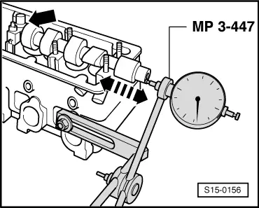
| Inlet valve opens | 7.5° after TDC |
| Inlet valve closes | 31.5° after BDC |
| Exhaust valve opens | 32.5° before BDC |
| Exhaust valve closes | 8.5°before TDC |
Note
|
|
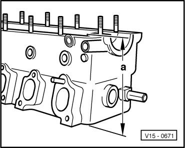
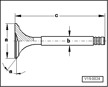
| Dimension | Inlet valve | Outlet valve | |
| Ø a | mm | 35,6 | 29,0 |
| Ø b | mm | 6,963 | 6,943 |
| c | mm | 94,8 | 95,0 |
| α | ∠° | 45 | 45 |